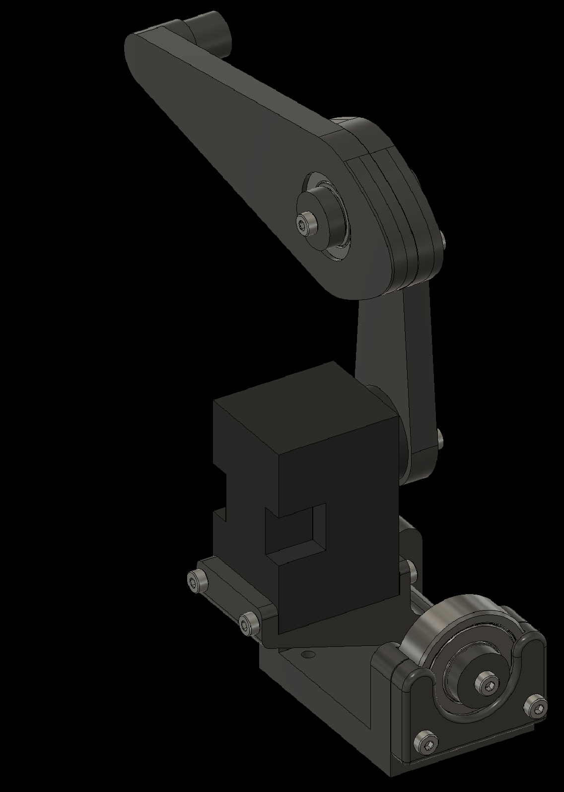
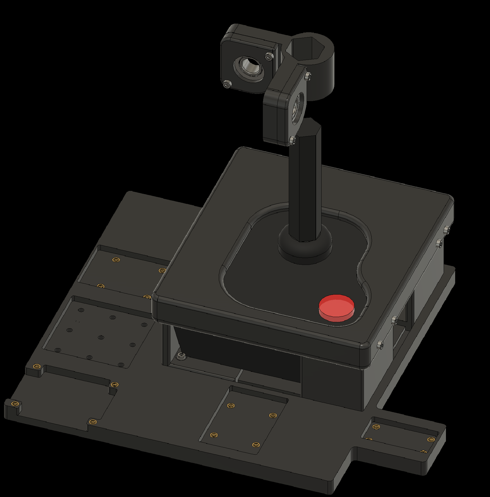
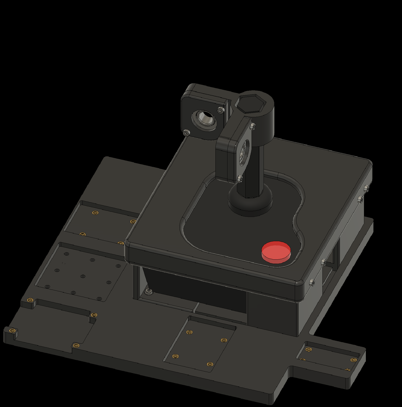
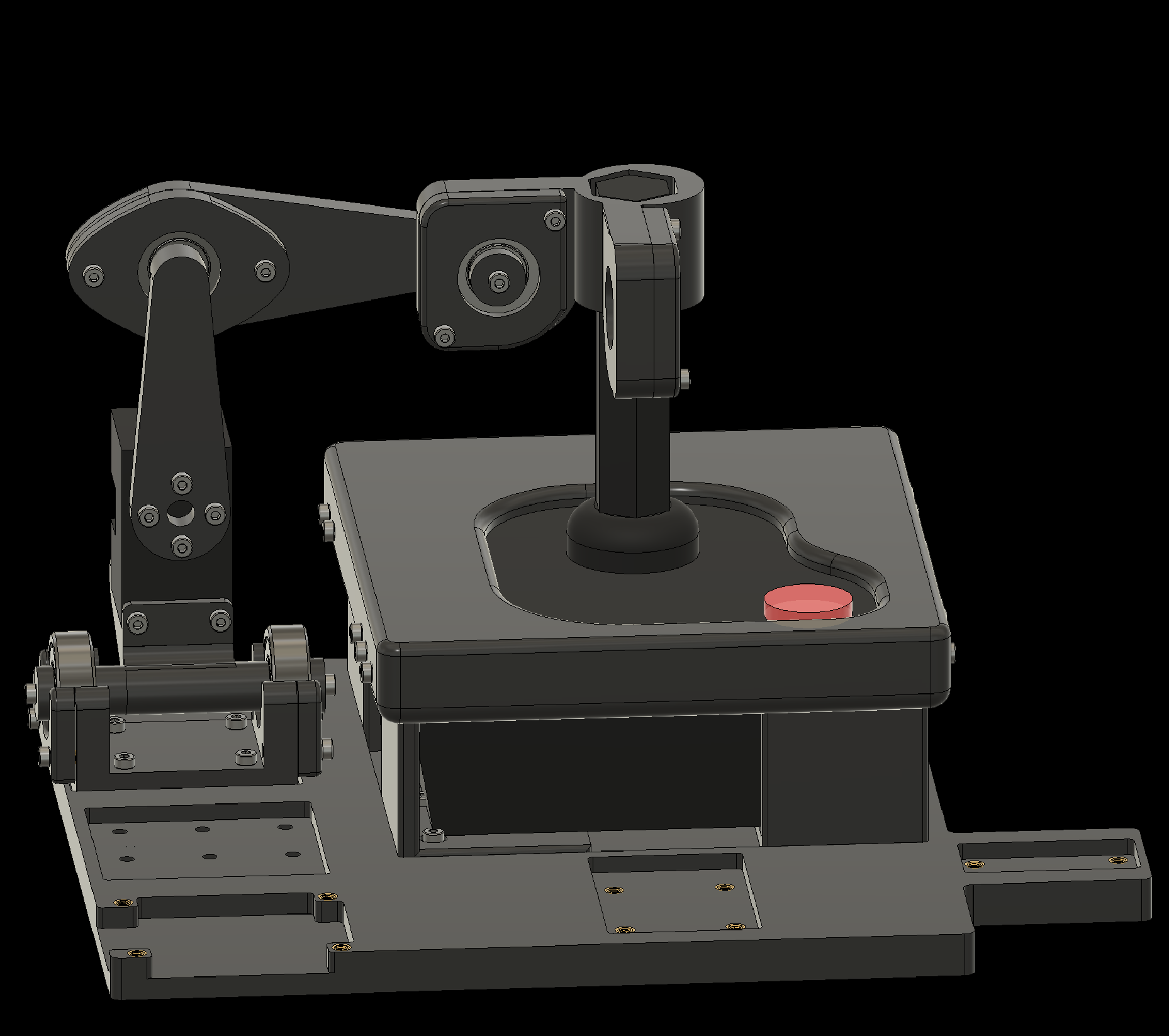
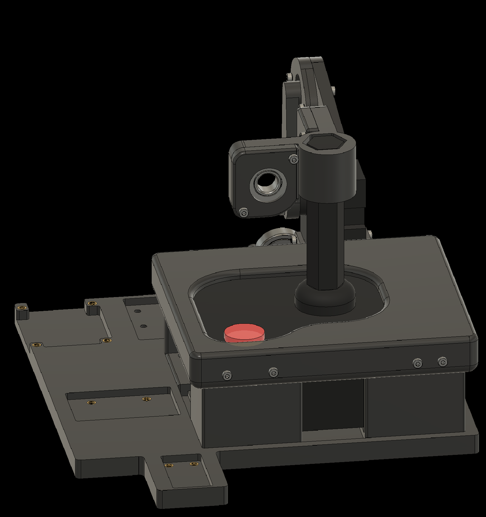
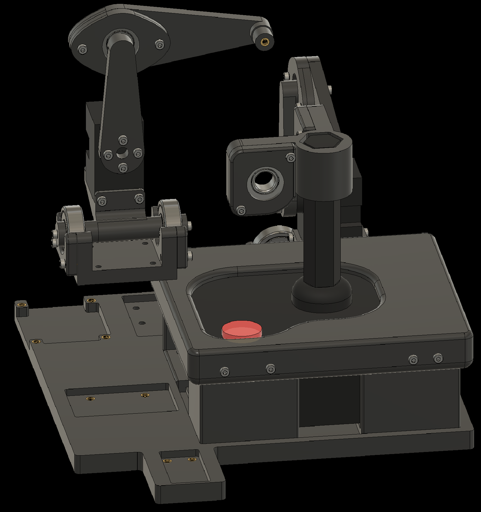
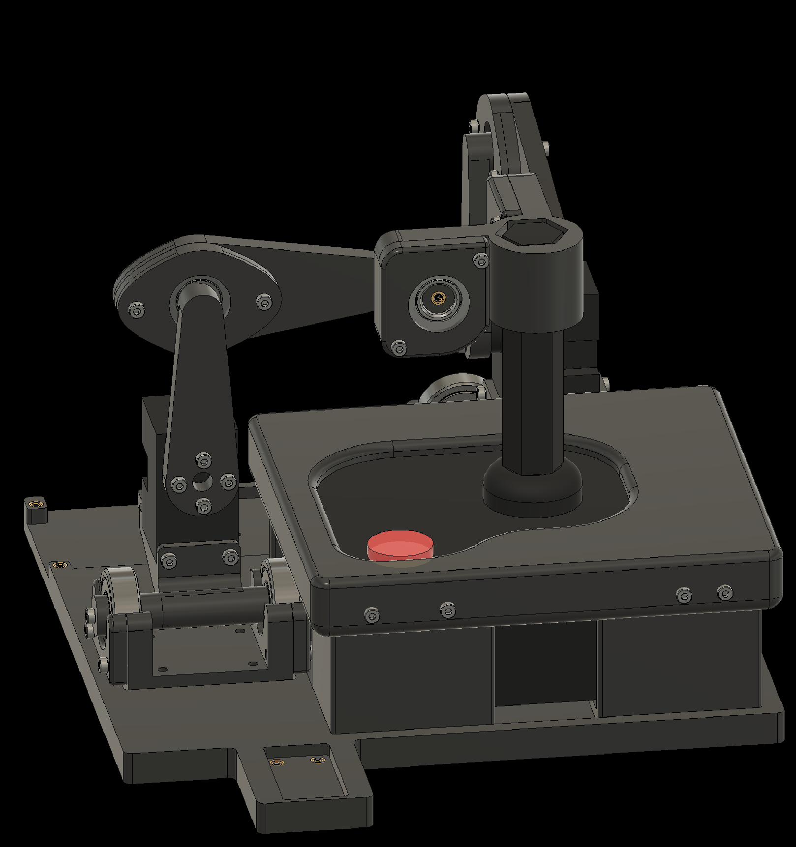
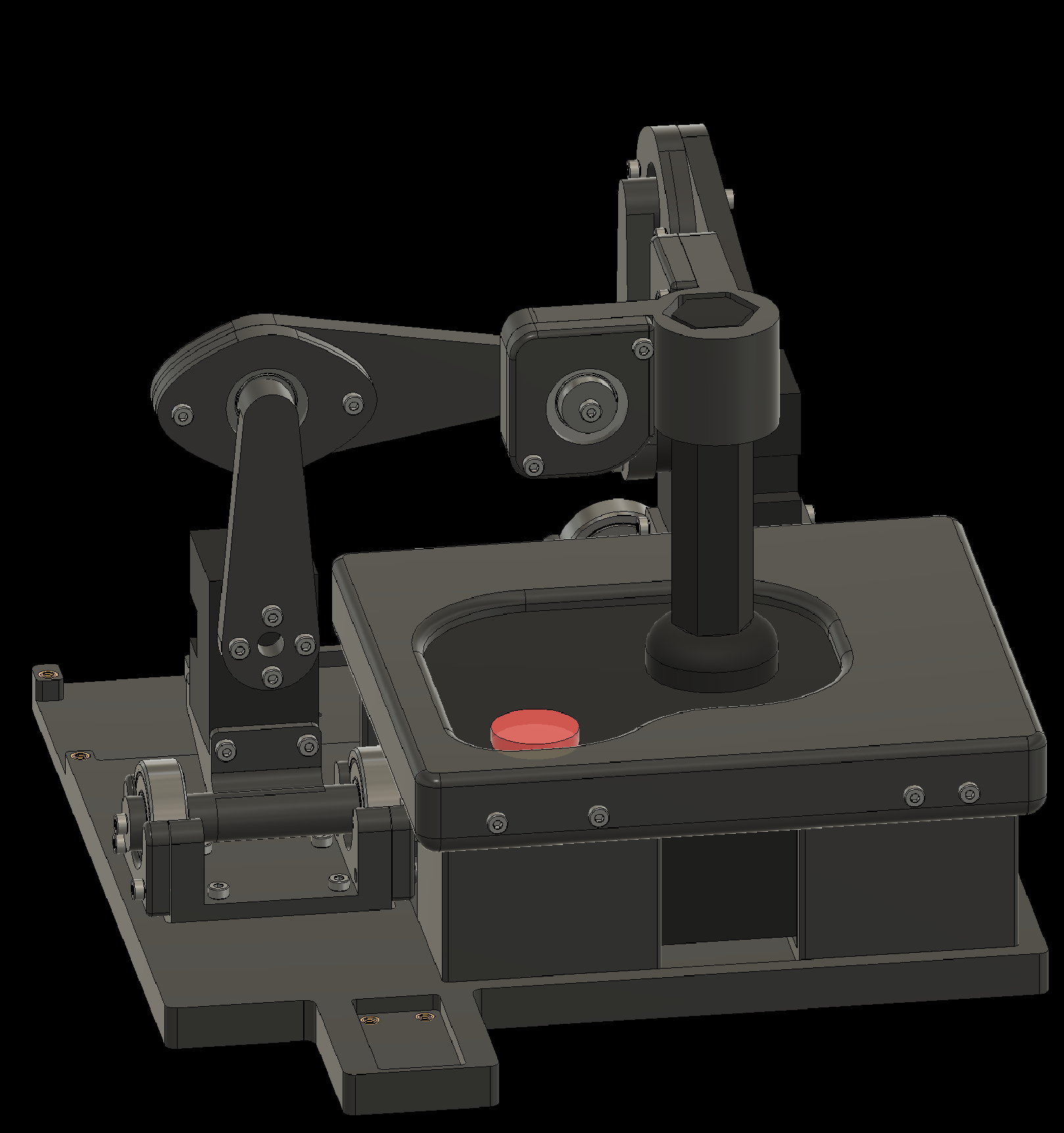
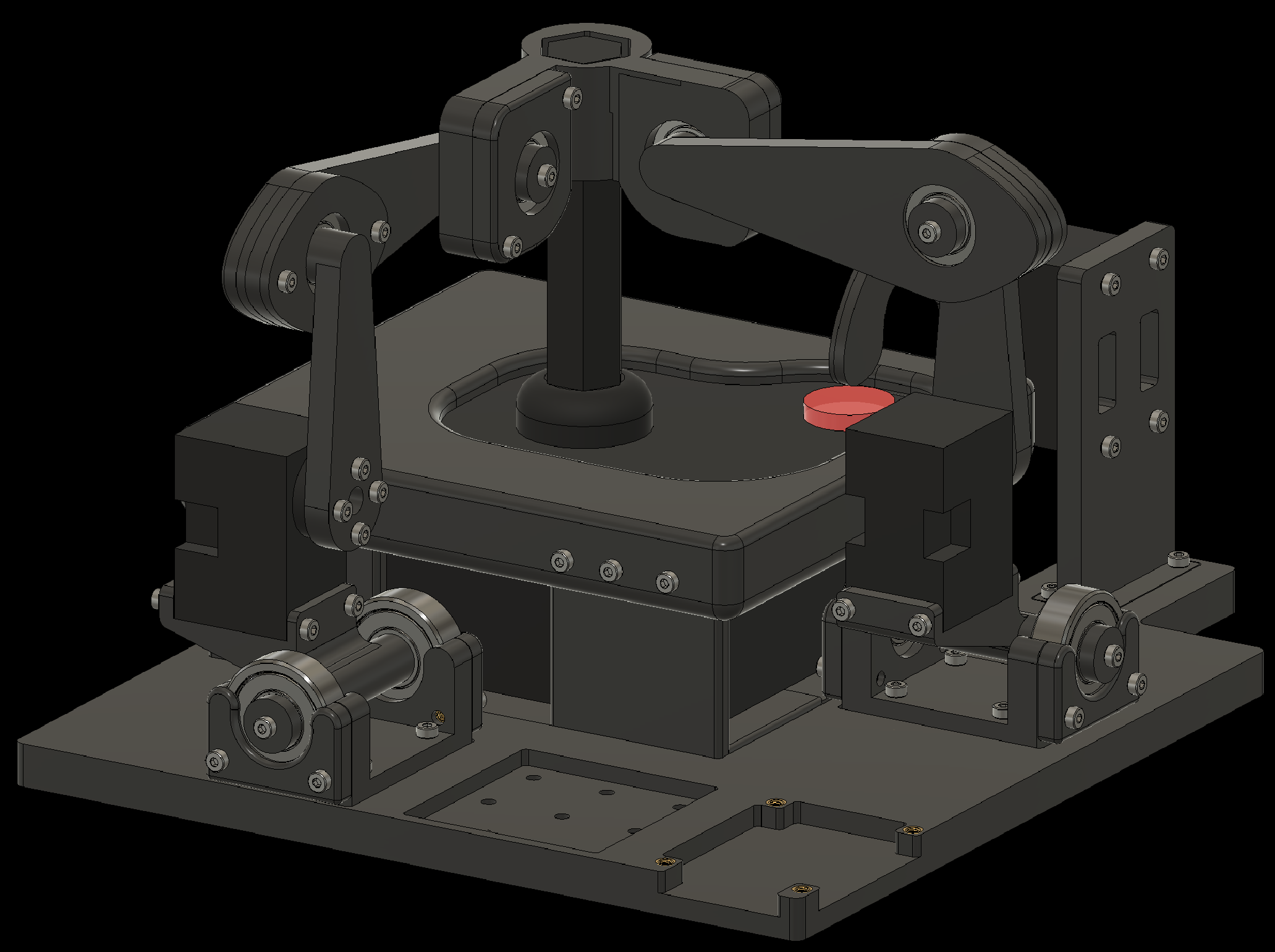
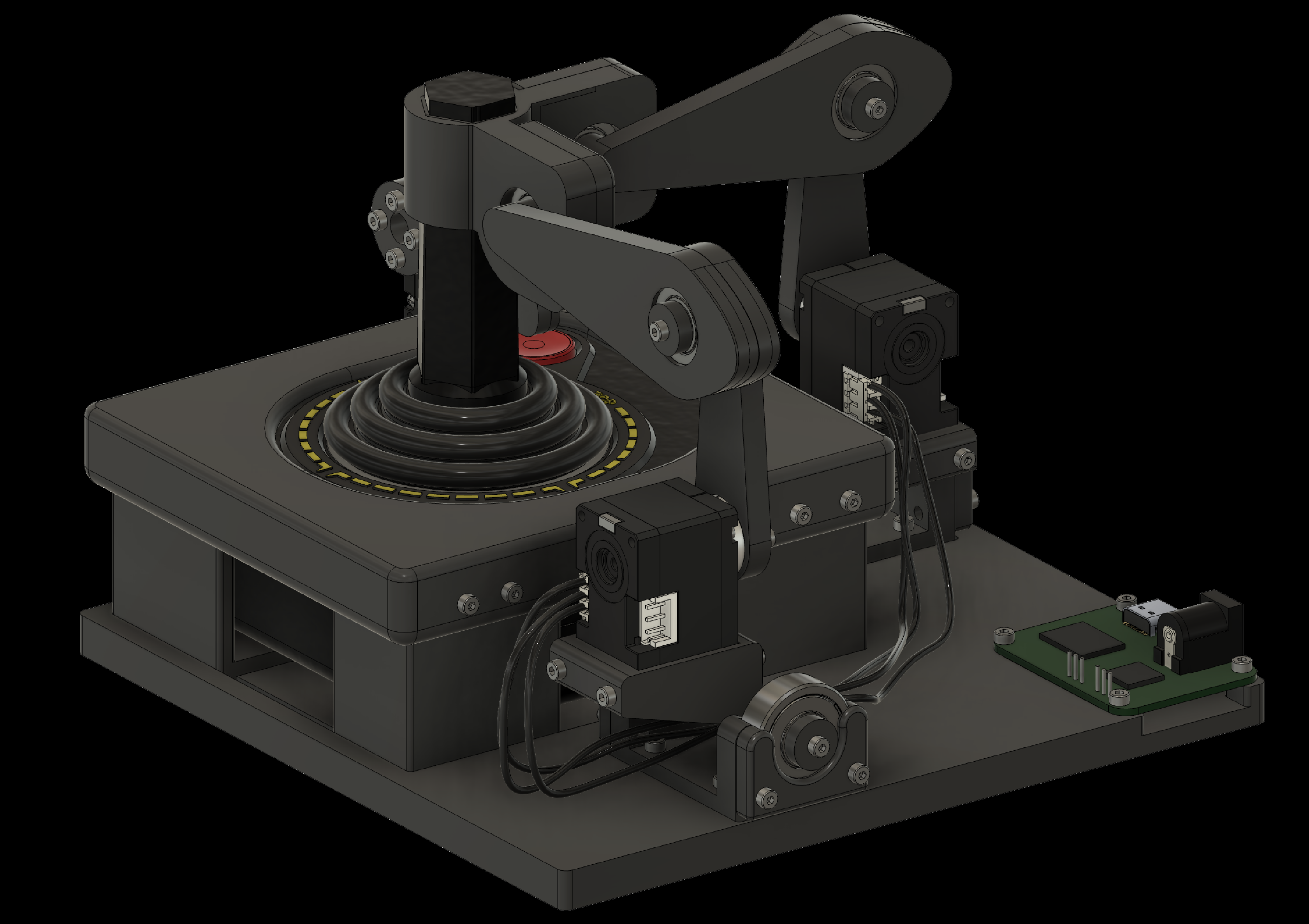
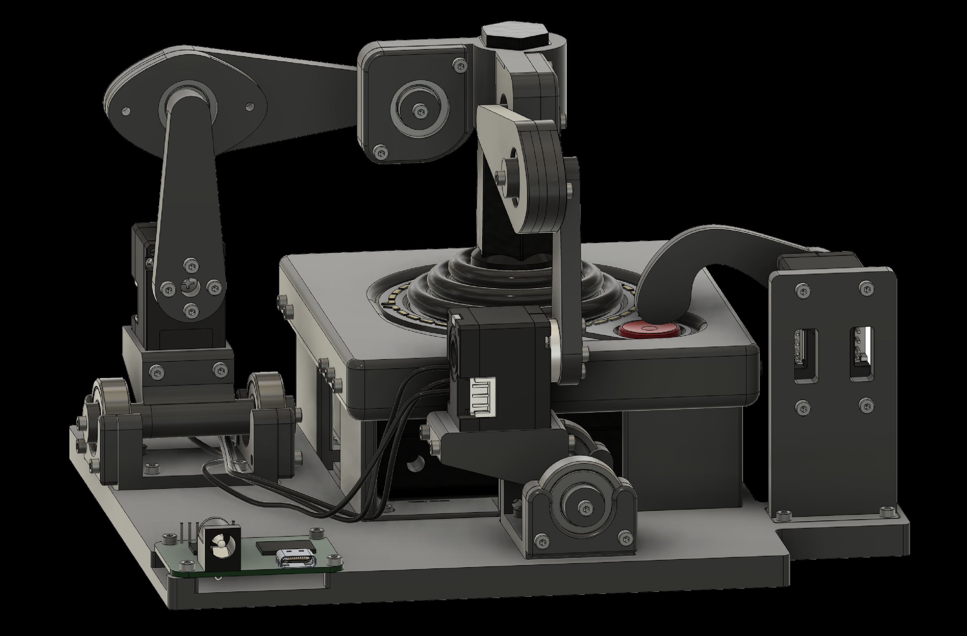
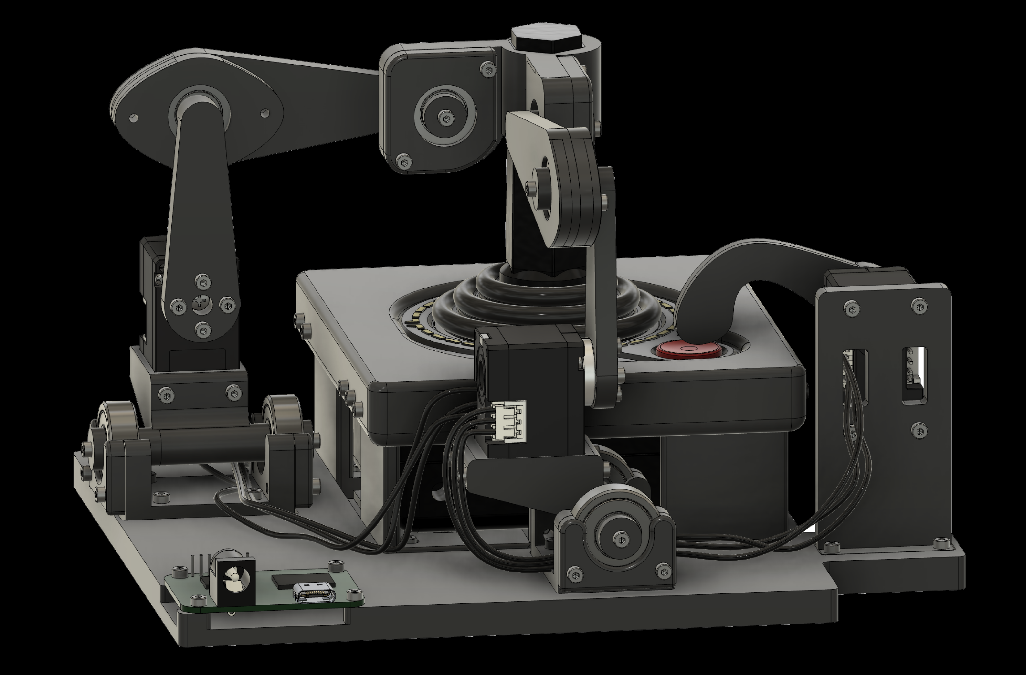
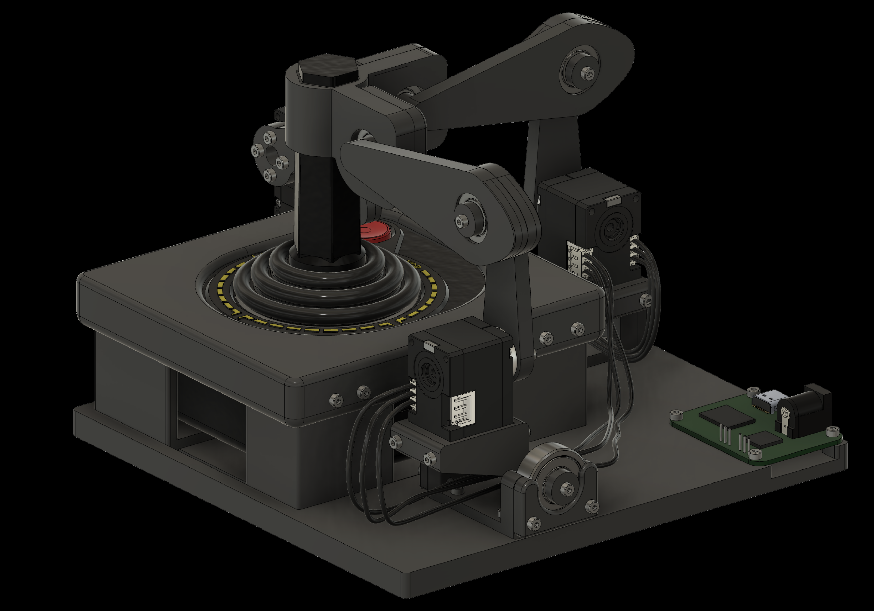
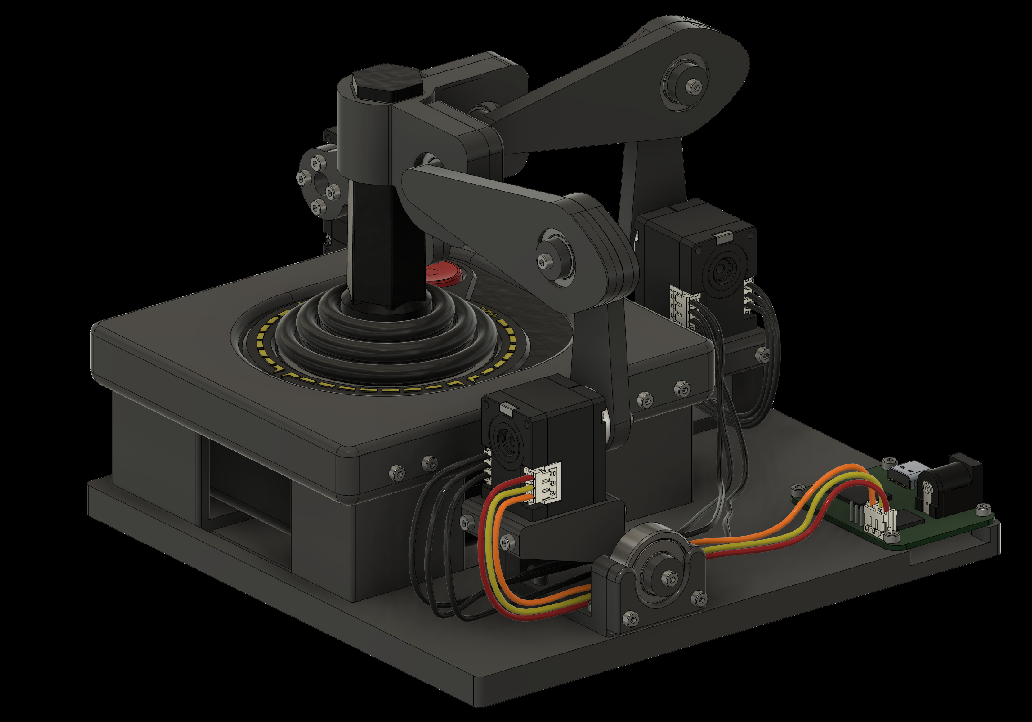
The Robotroller consists of two types of parts. The first type is custom parts designed in CAD software (Autodesk Fusion) that have to be manufactured. We designed these parts so they can be printed on a consumer 3D printer, like the Bambu Lab P1S, using an inexpensive filament, such as PLA. The second type is parts that are commercially available. These include screws, bearings, servos, threaded inserts, and electronics. The fully assembled Robotroller is shown above. The parts to print and parts to buy are listed below, with the assembly guide at the end.
Parts to print
Parts to buy
Assembly guide
Robotroller Assembly Guide
Use arrow keys, or tap or click either side of the slide
Overview
- 3D printing the components
- Adding threaded inserts to the components
- Assembling individual components
- Attaching components to the baseplate
- Wiring the components
- Testing the Robotroller
1. 3D Printing the Components
Most components can be printed without support. Use a high infill for stronger parts—85% with either a grid or cuboid infill pattern works well. The parts that need support are:
- Joystick holder
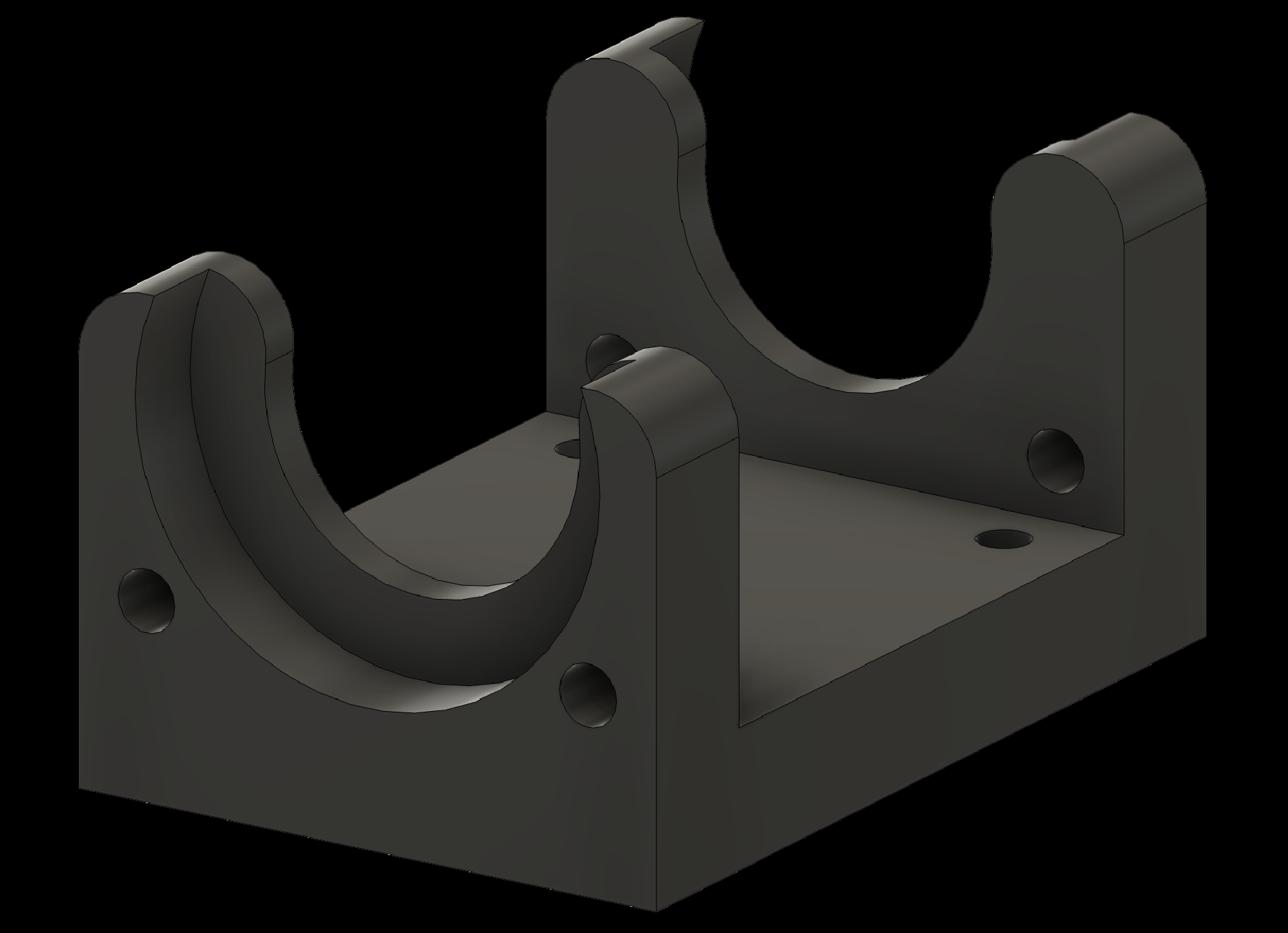
- Shoulder socket
- Fire finger holder
Use tree supports that originate from the build plate. A threshold angle of 35 degrees in Bambu Studio works well.
2. Adding Threaded Inserts to the Components
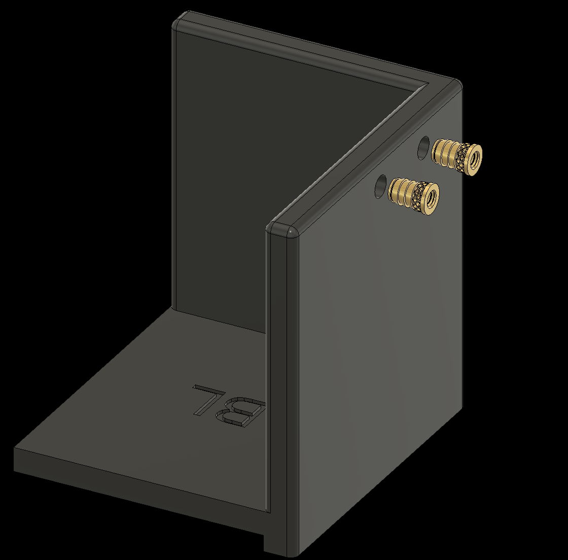
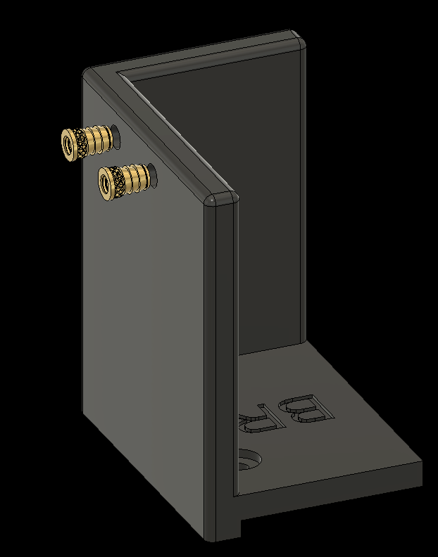
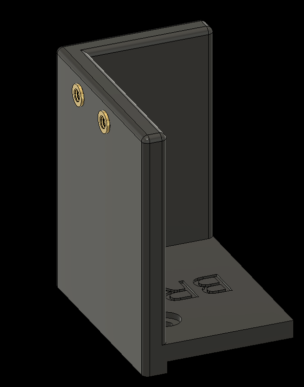
Heat-set the threaded inserts using a soldering iron. The following slides show which components need inserts and where to place them.
2. Adding Threaded Inserts to the Components
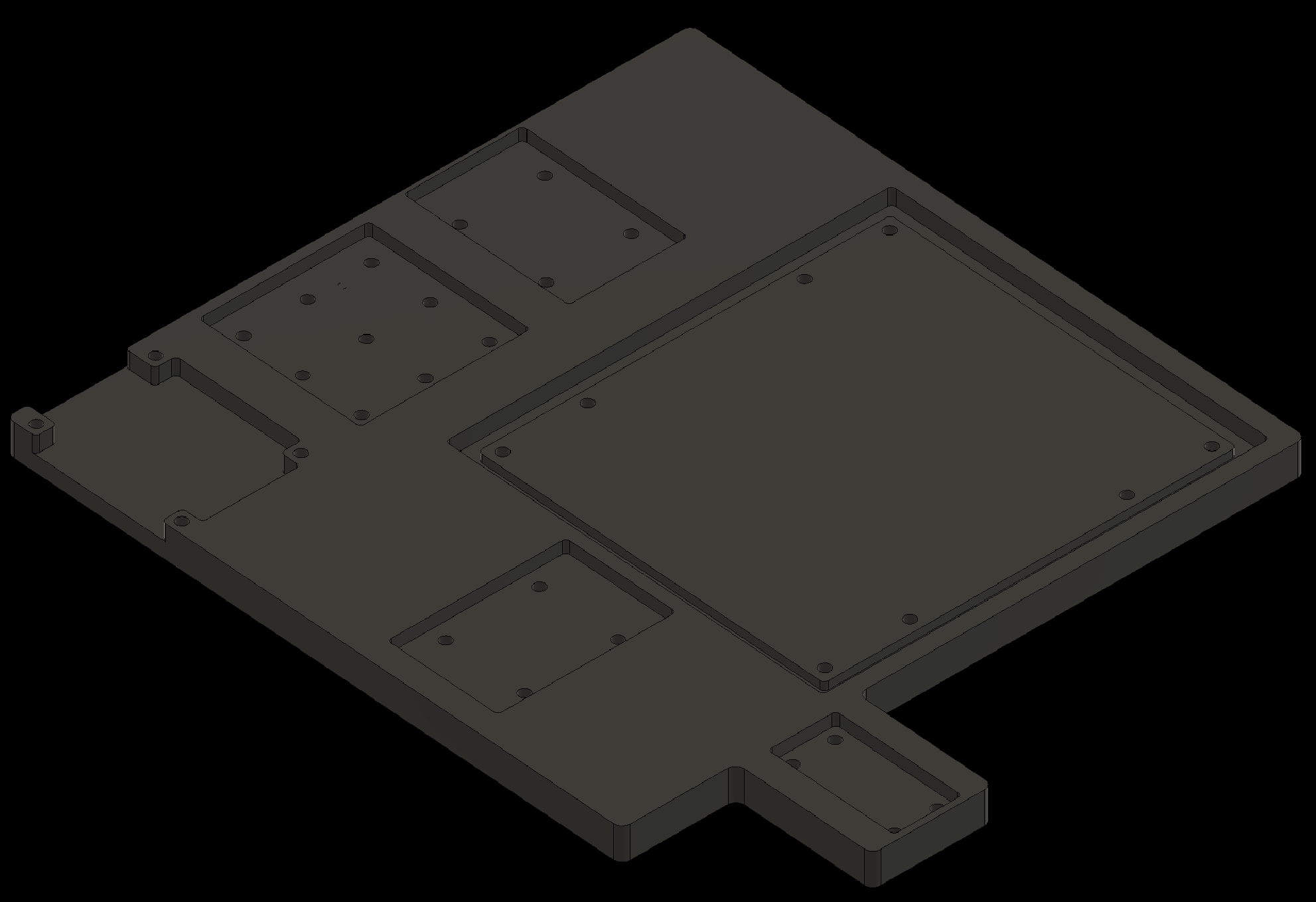
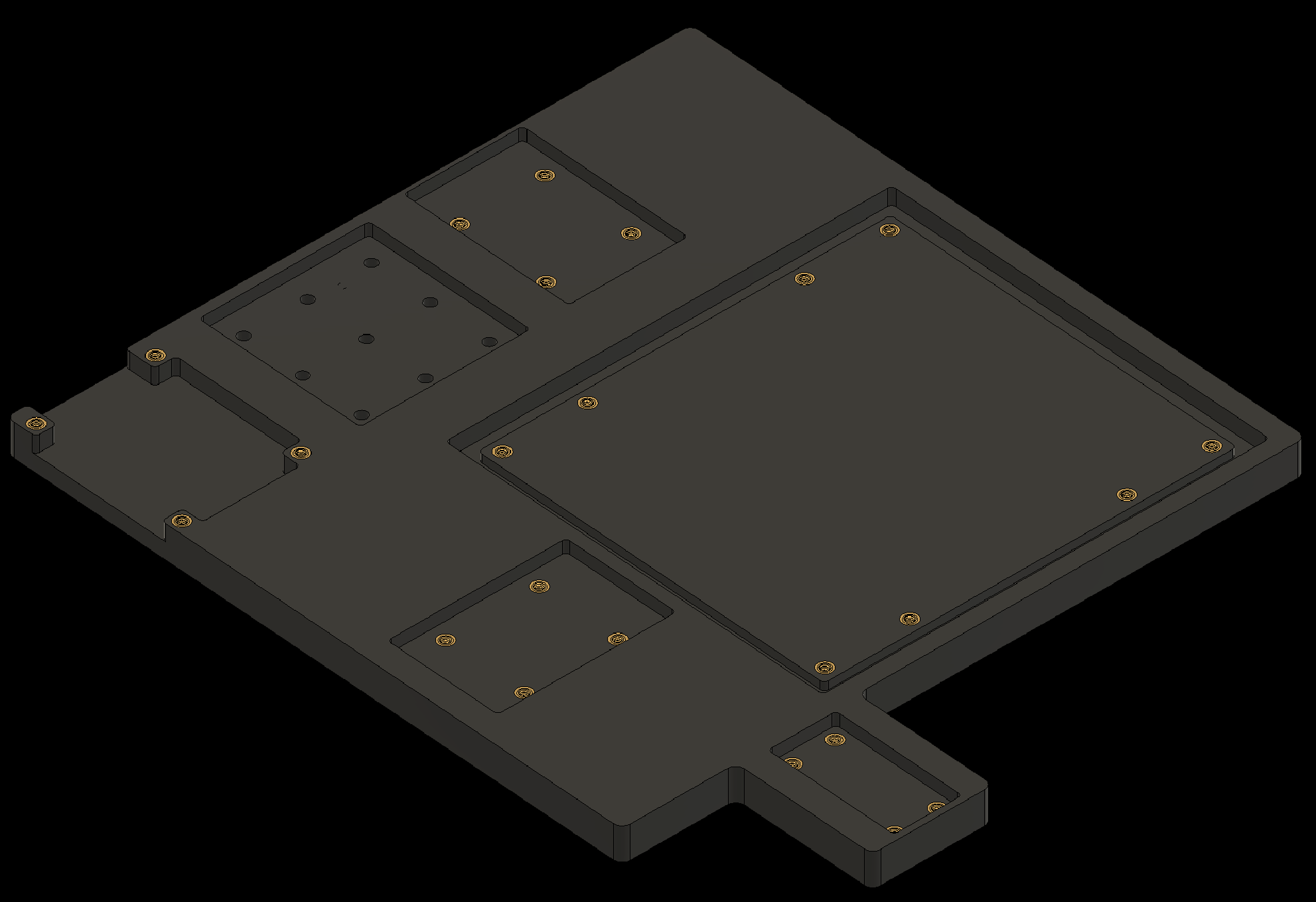
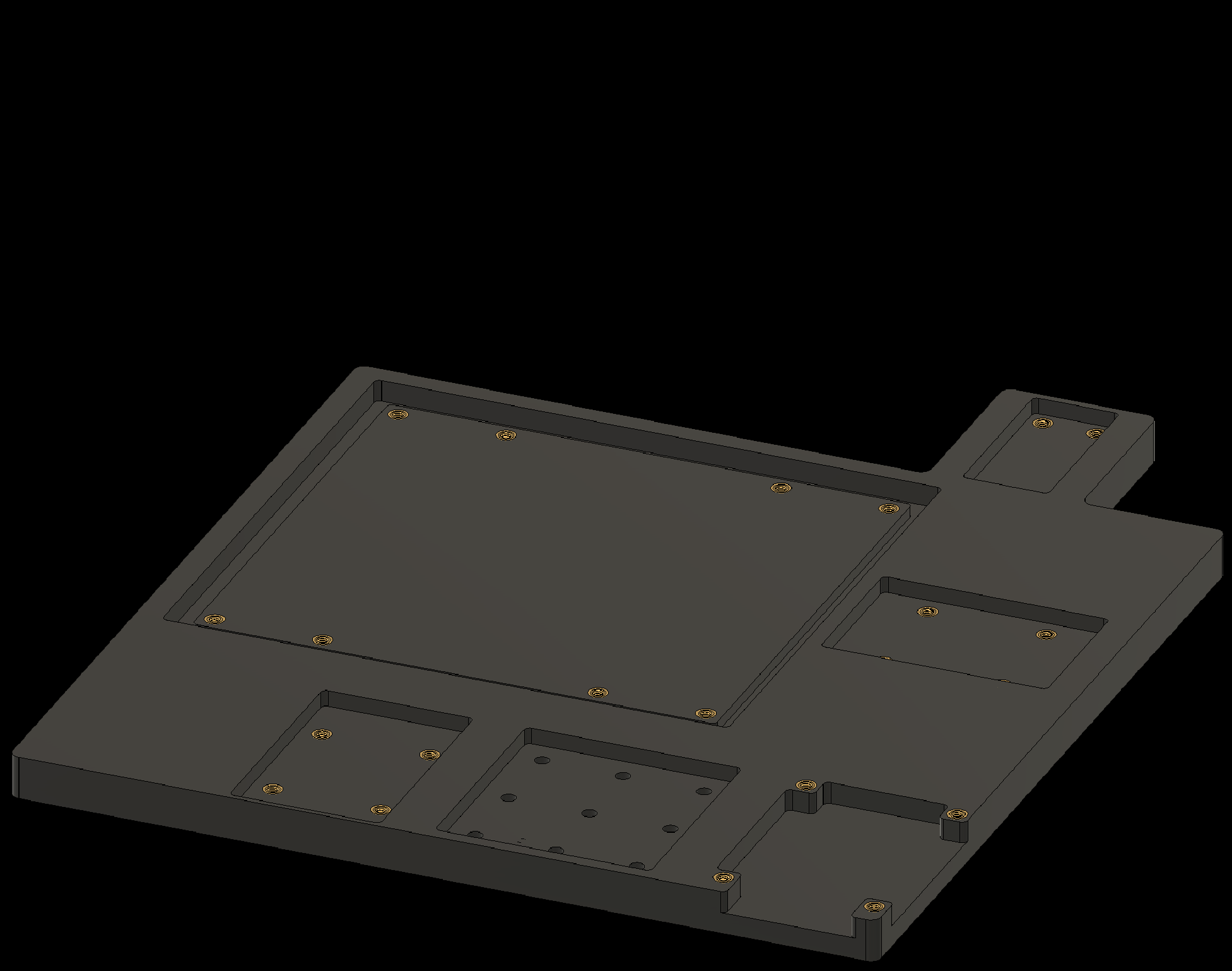
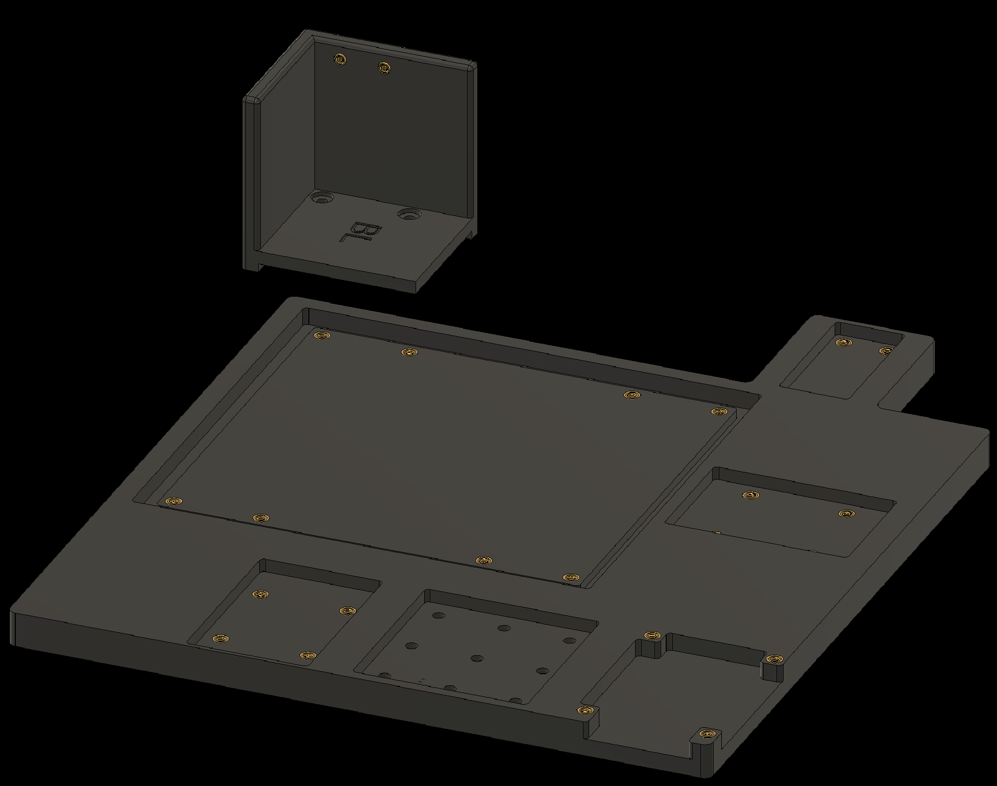
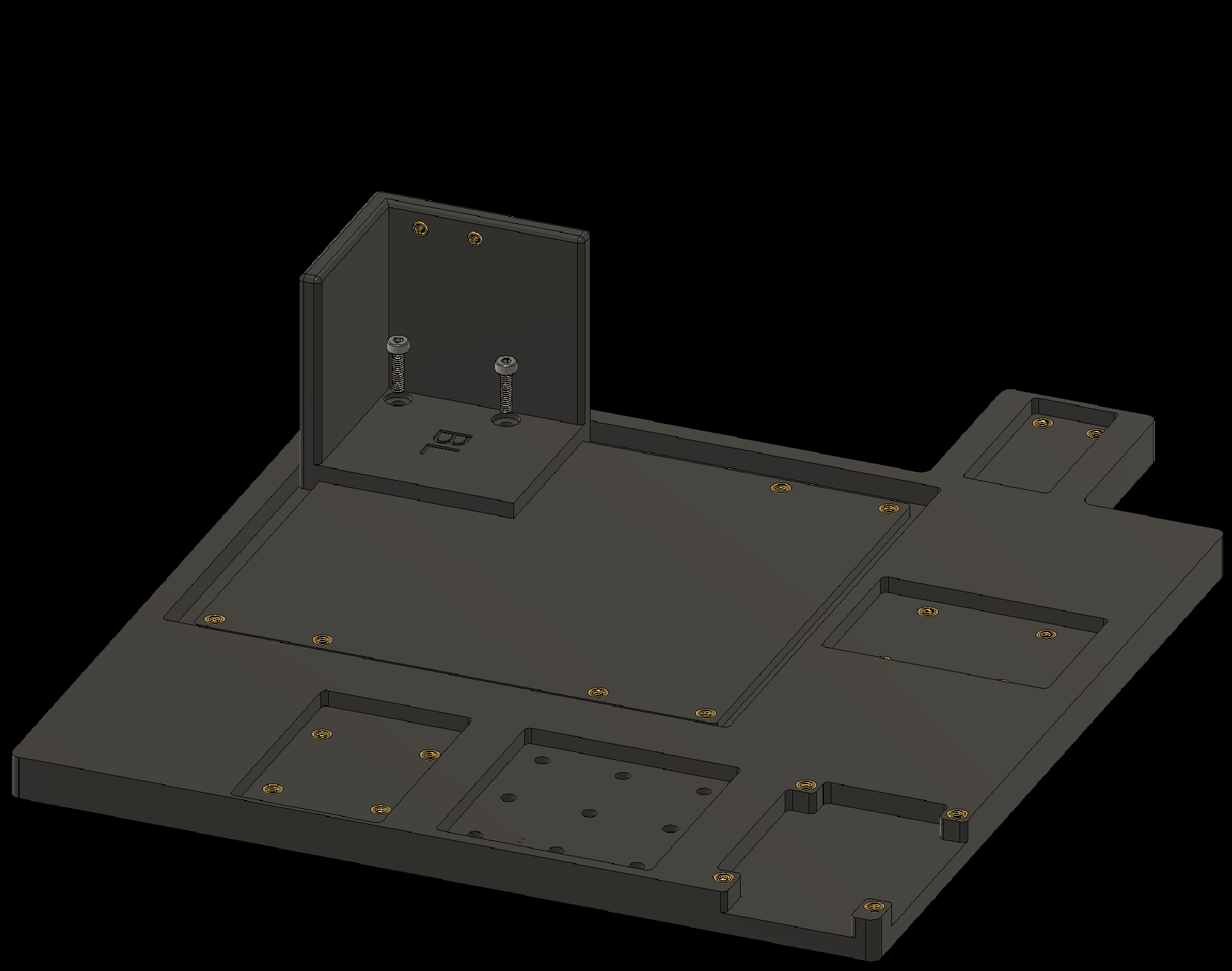
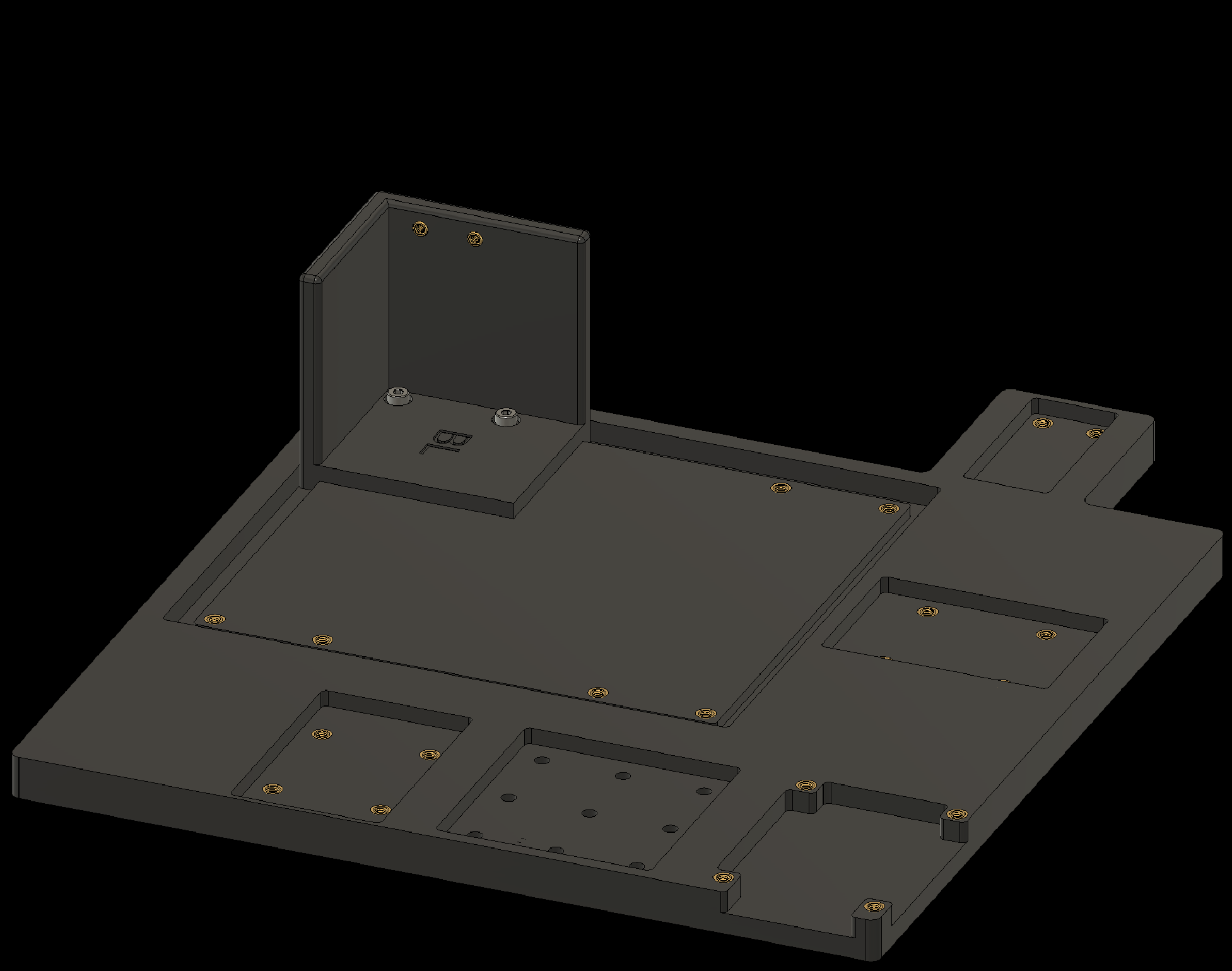
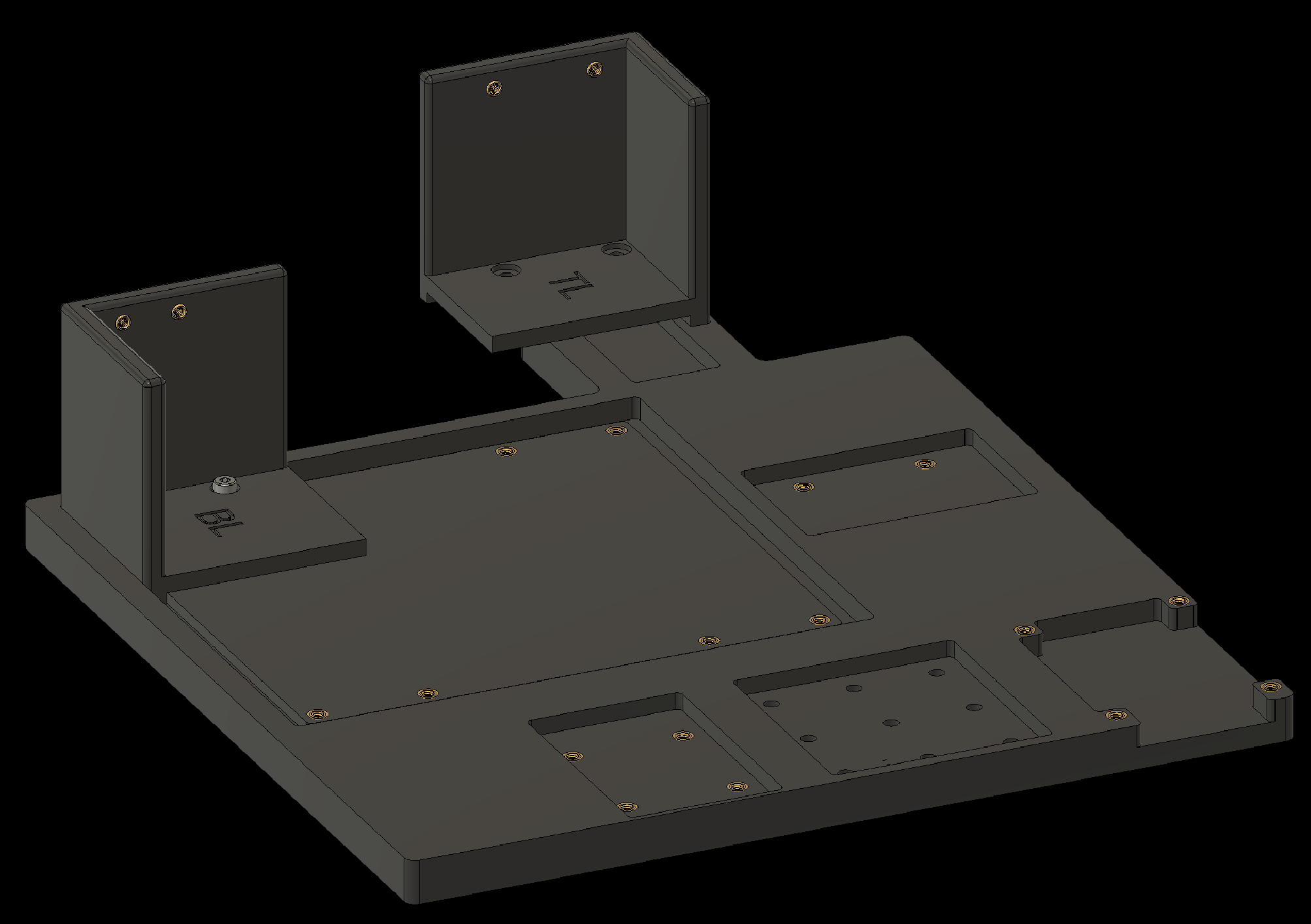
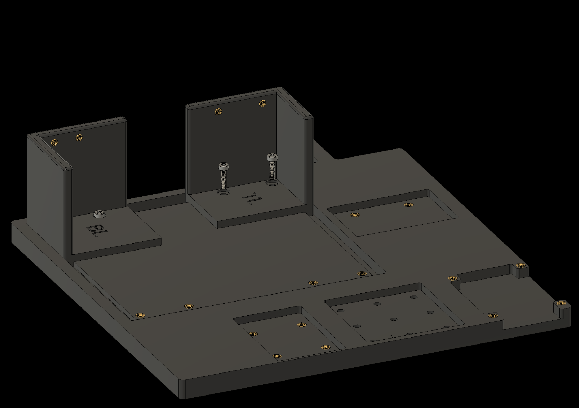
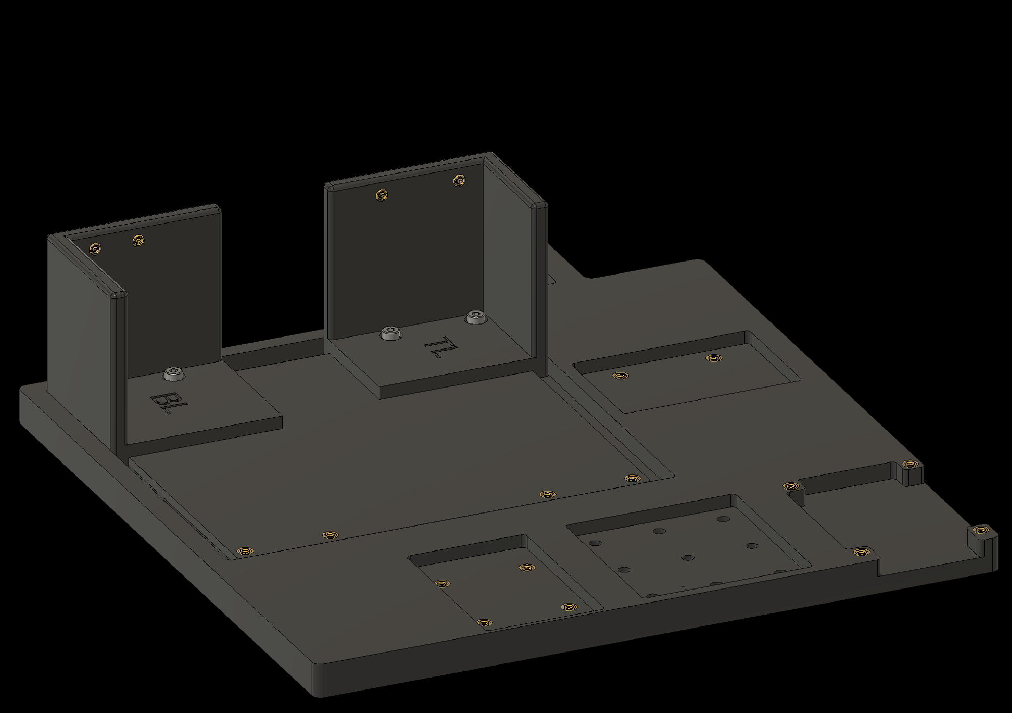
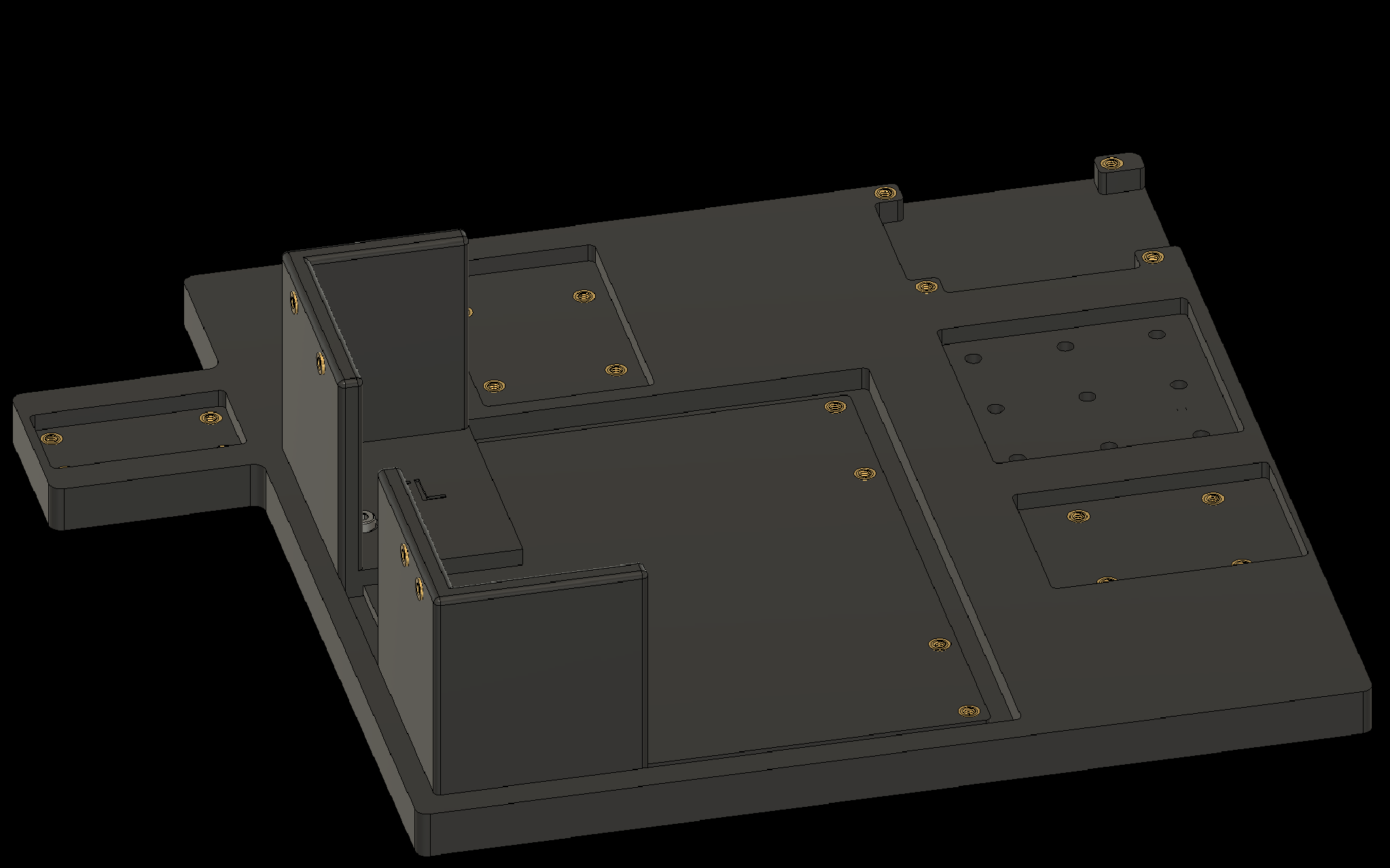
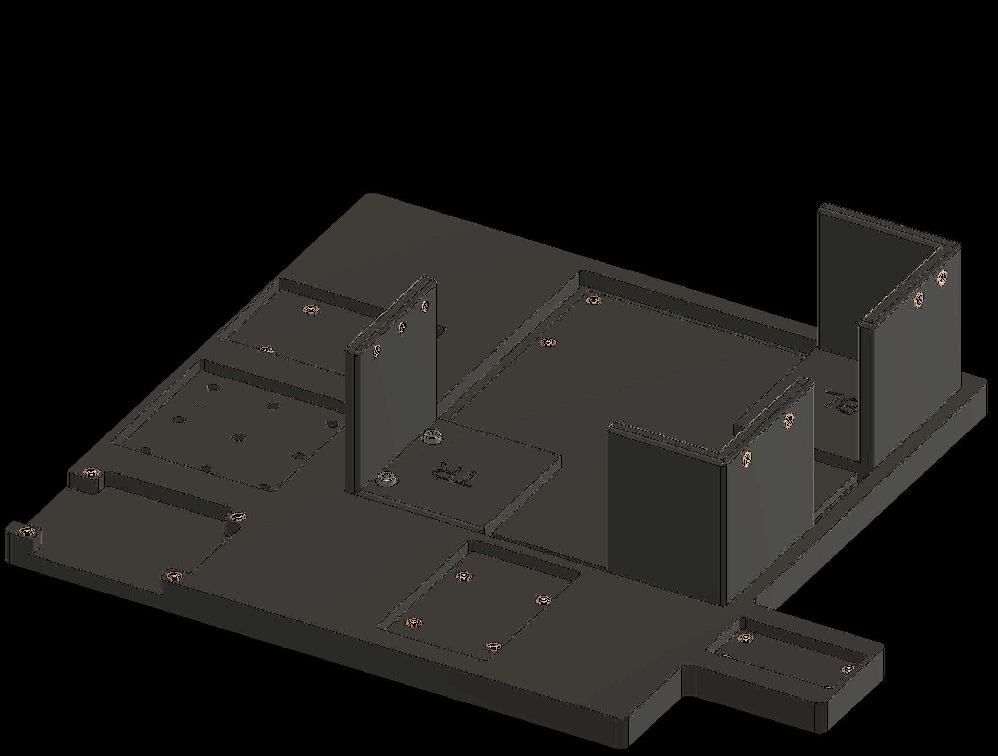
2.1 Add threaded inserts to the baseplate

2. Adding Threaded Inserts to the Components
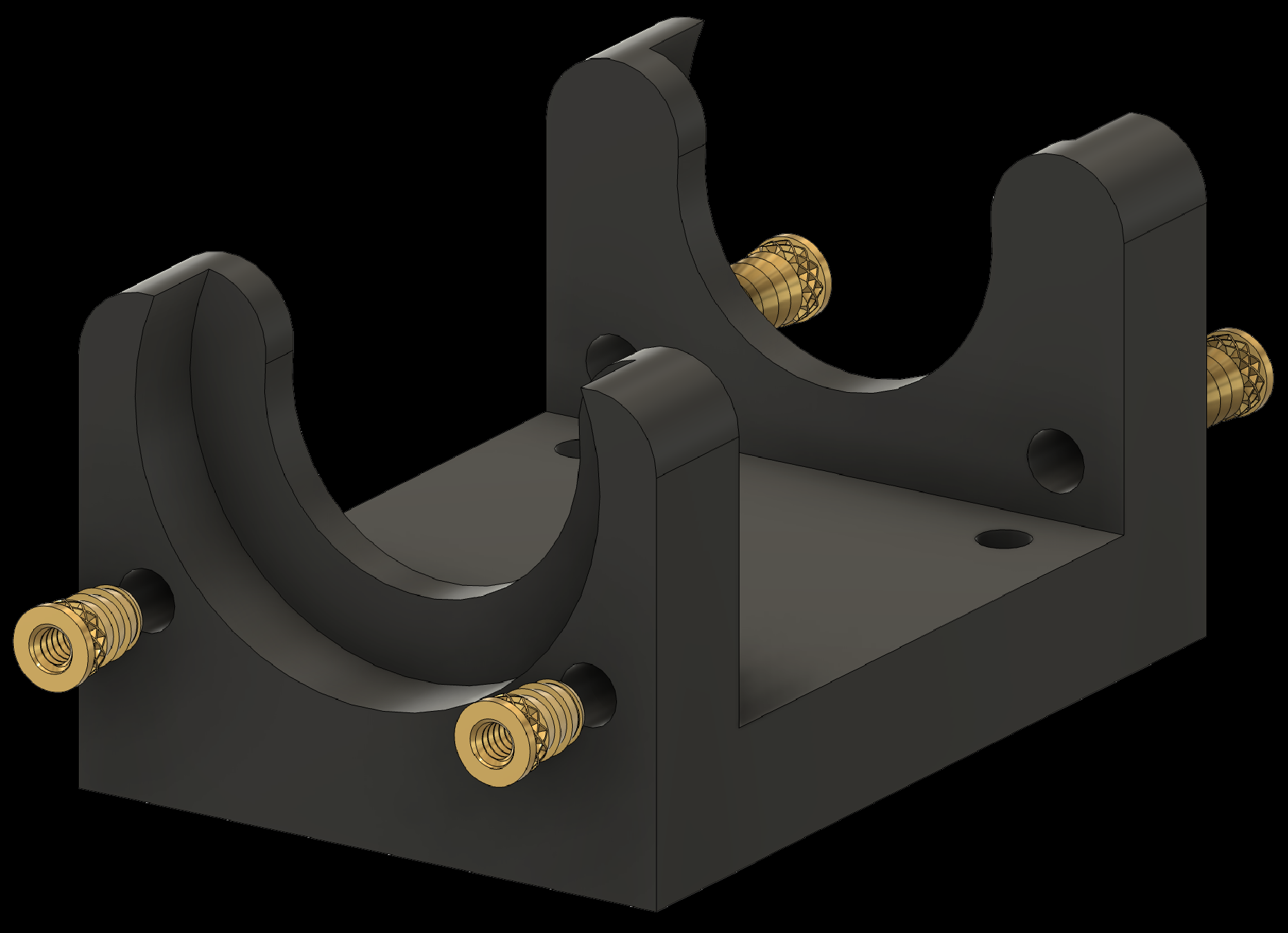
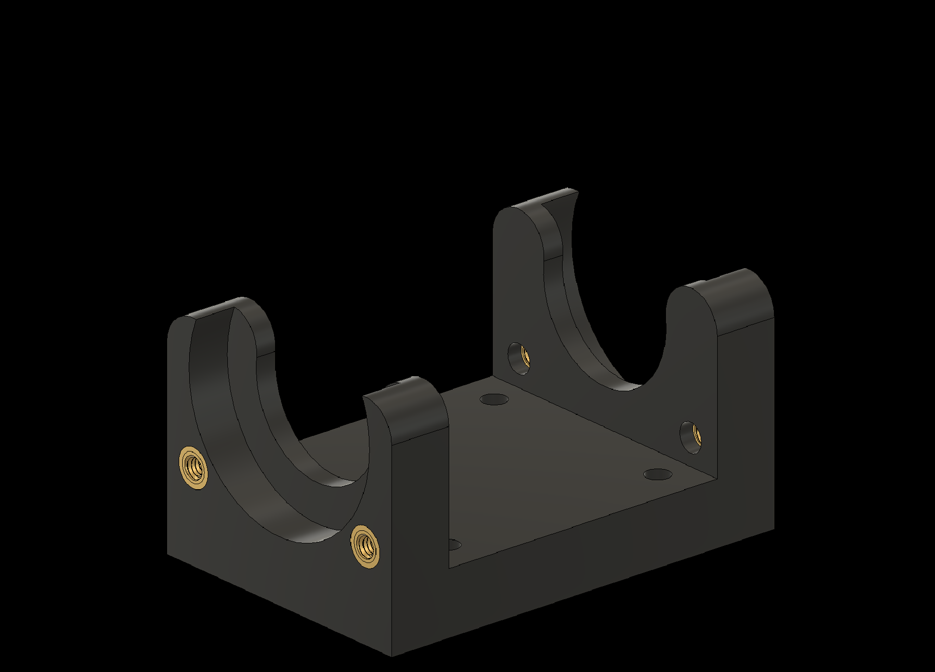
2.2 Add threaded inserts to the Shoulders (2x)
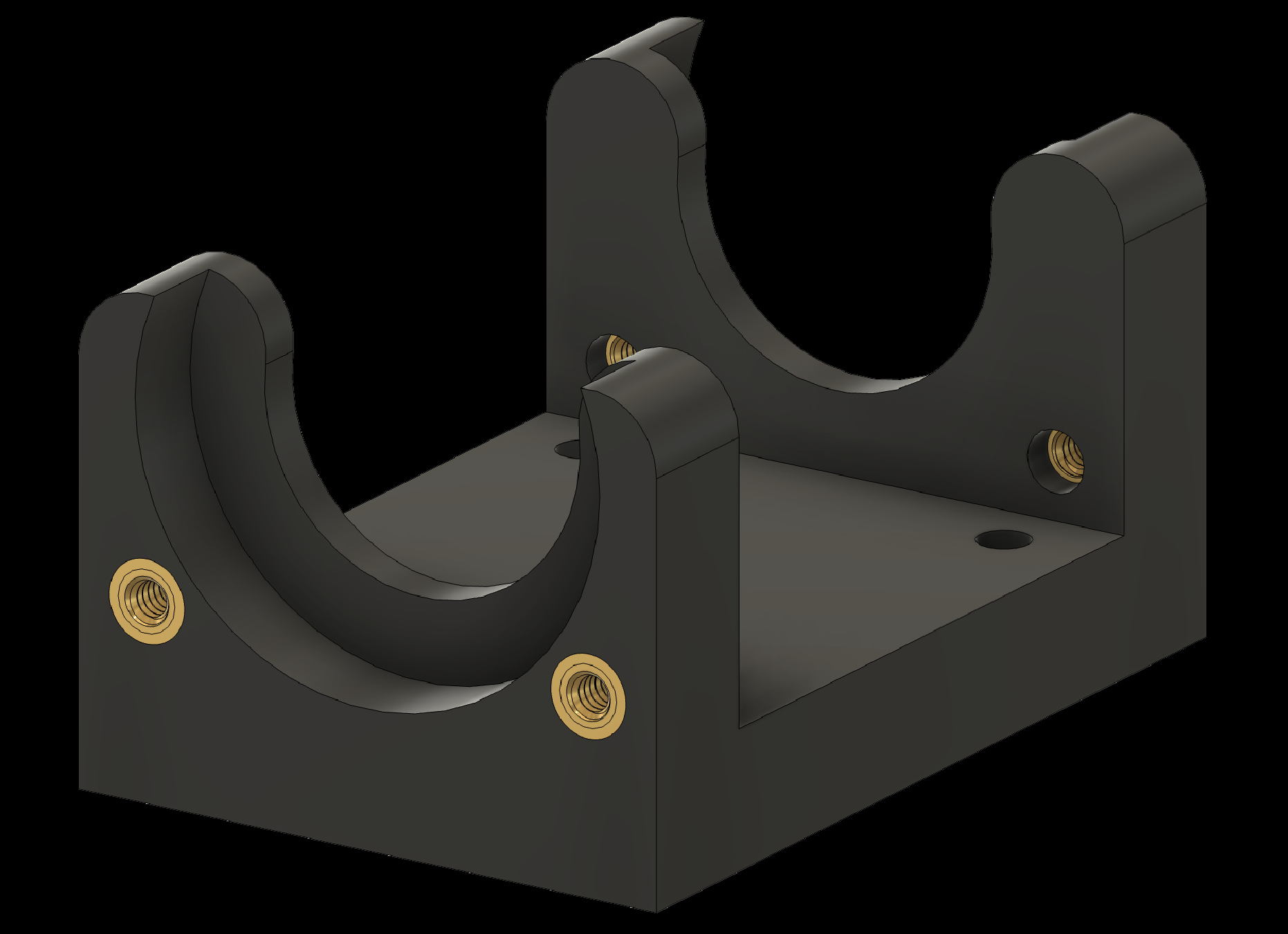
2. Adding Threaded Inserts to the Components
2.3 Add threaded inserts to the Shoulder Joints (2x)

2. Adding Threaded Inserts to the Components
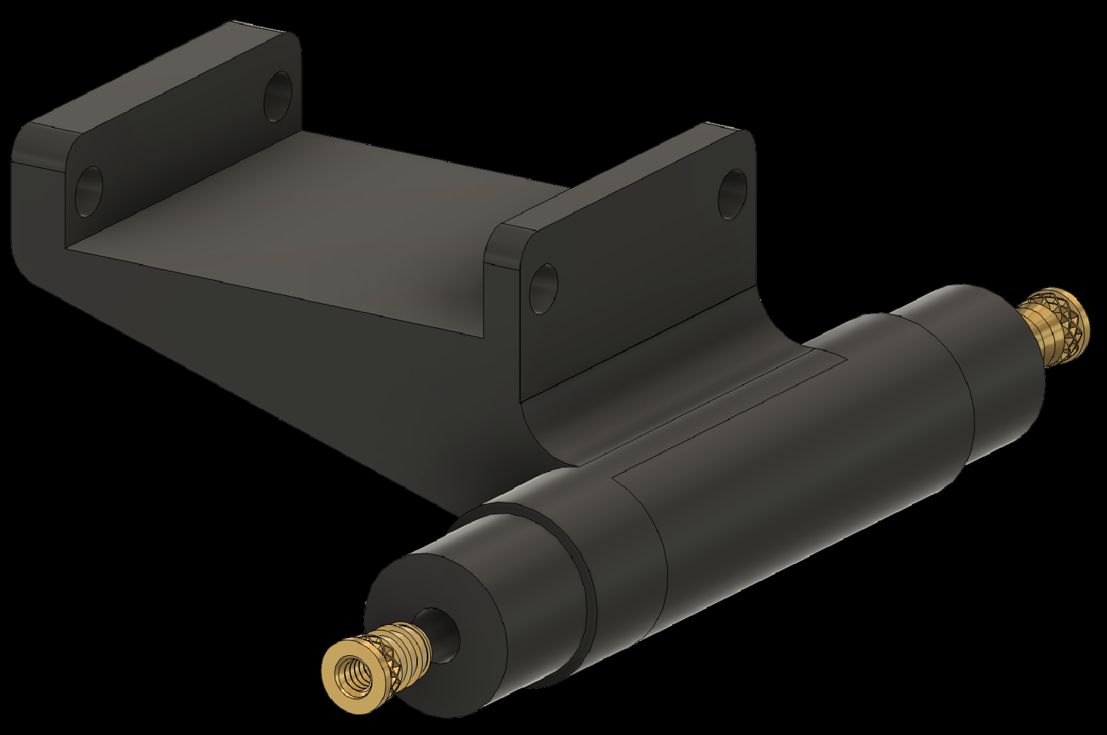
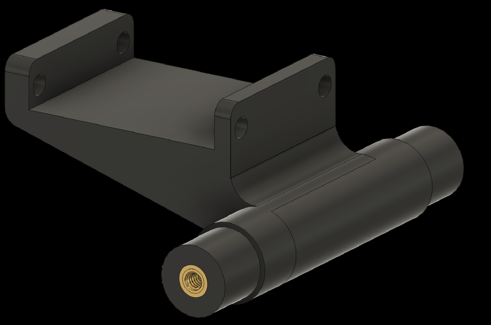
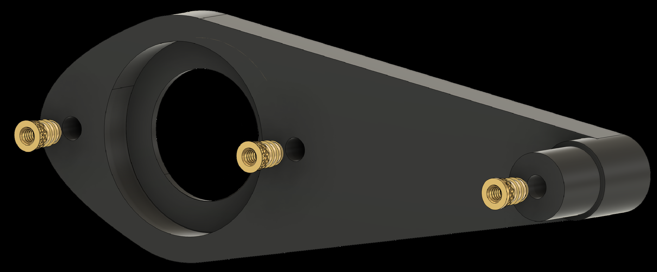
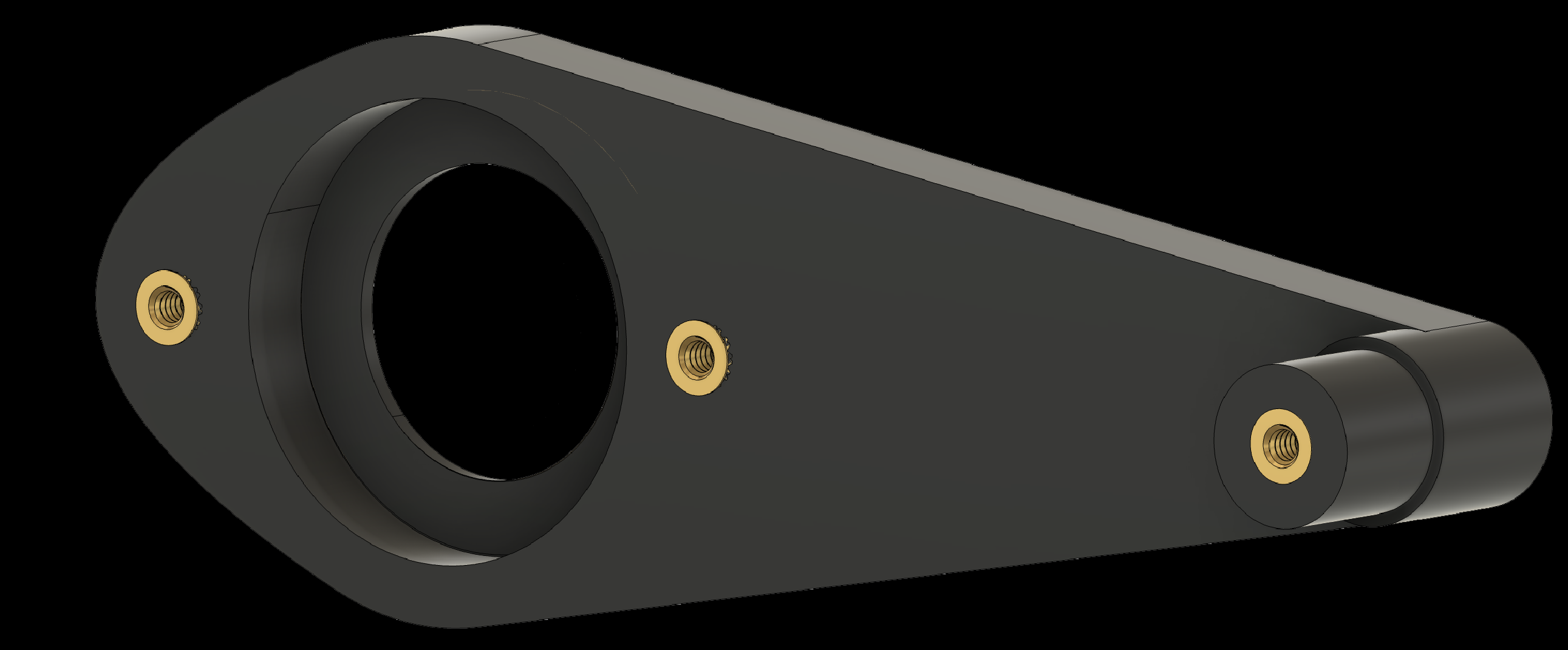
2.4 Add threaded inserts to the Elbow-to-Finger components (2x)
2. Adding Threaded Inserts to the Components
2.5 Add threaded inserts to the Joystick Attachment
2. Adding Threaded Inserts to the Components
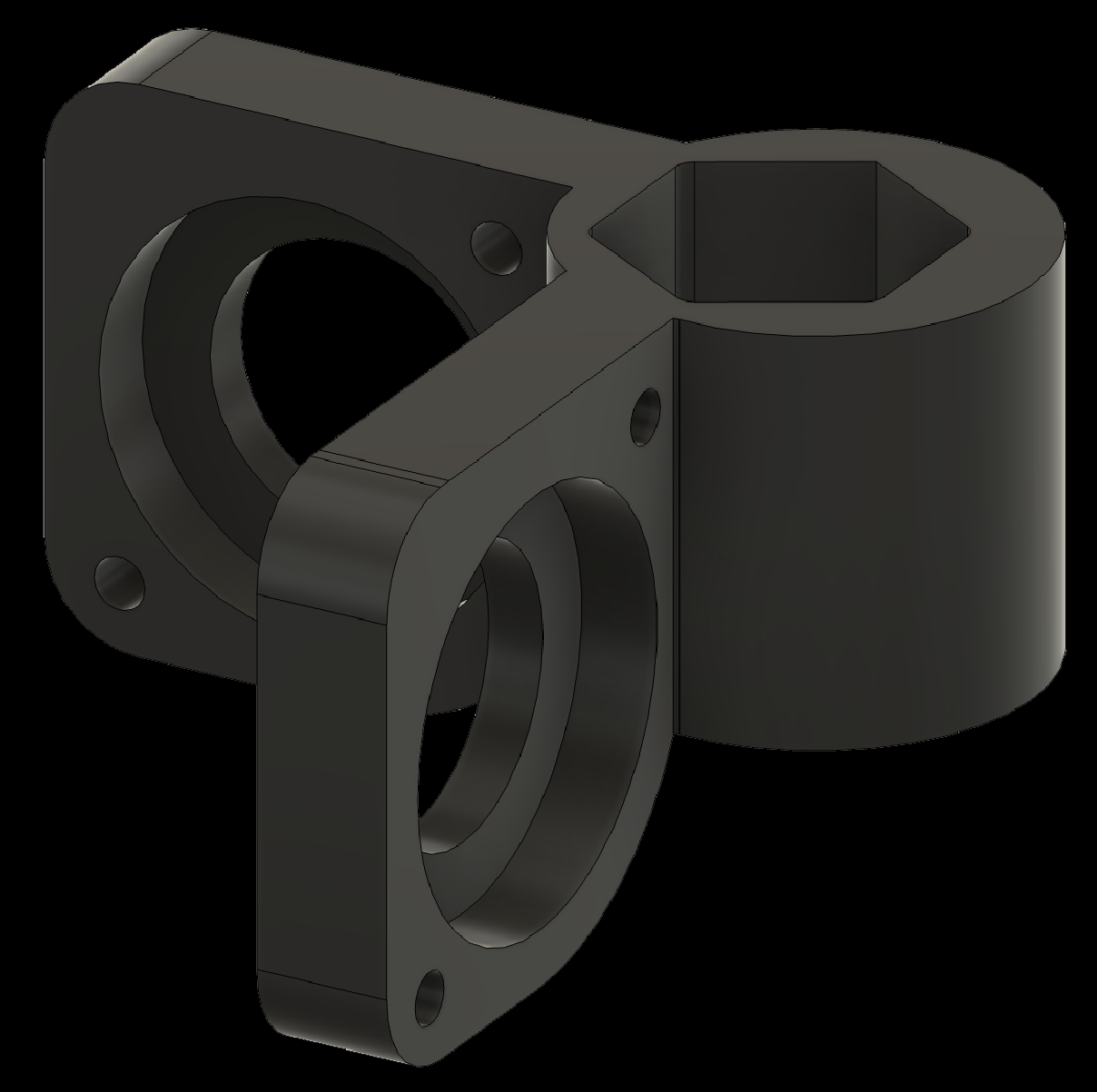
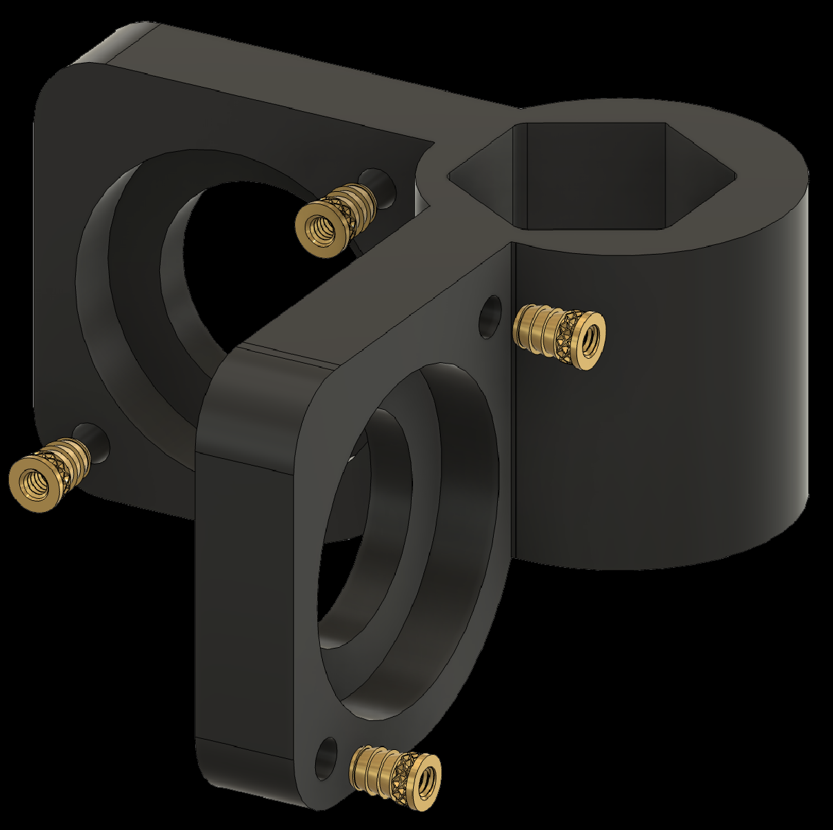
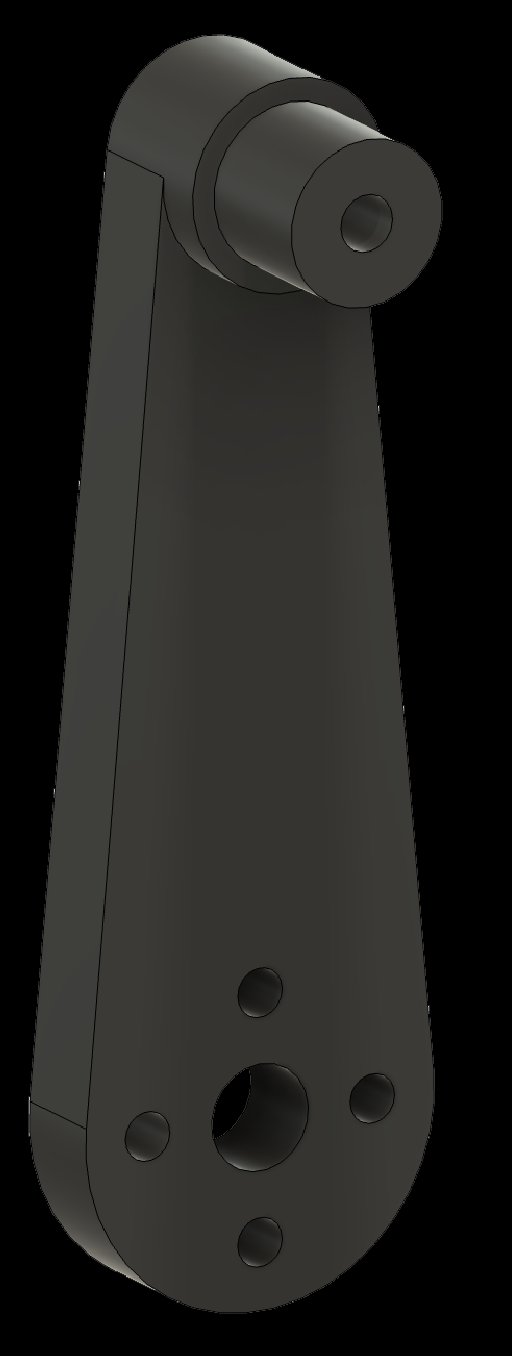
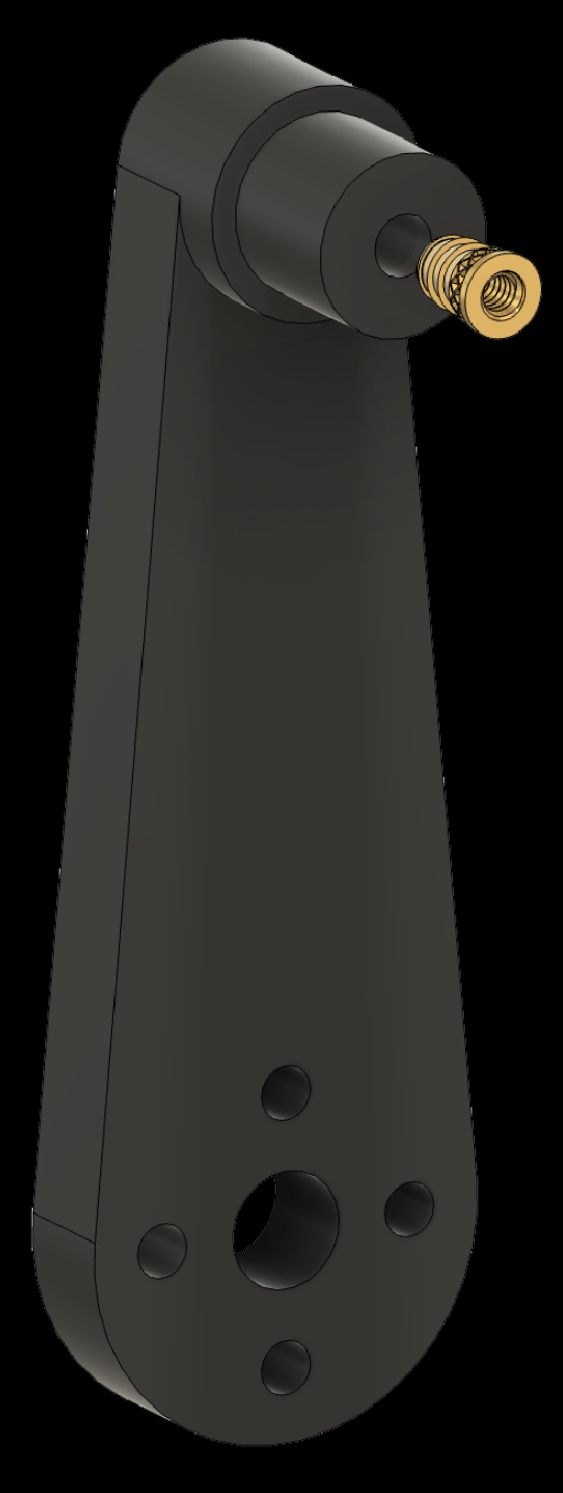
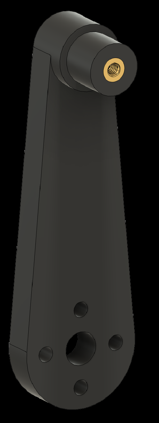
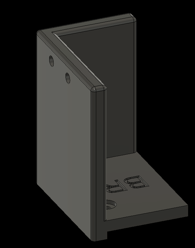
2.6 Add threaded inserts to the Motor Attachments (2x)
2. Adding Threaded Inserts to the Components
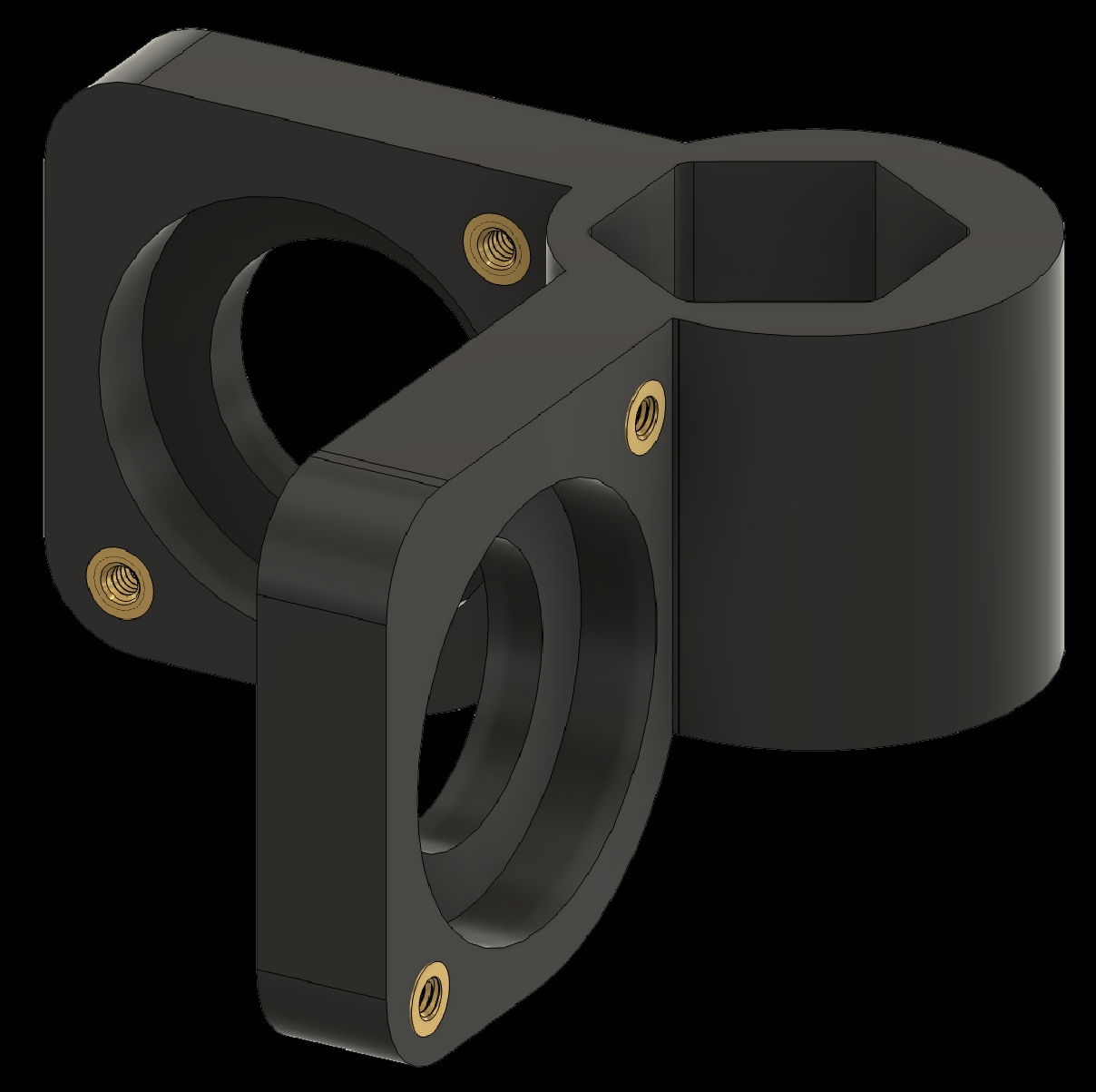
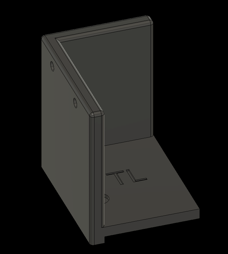
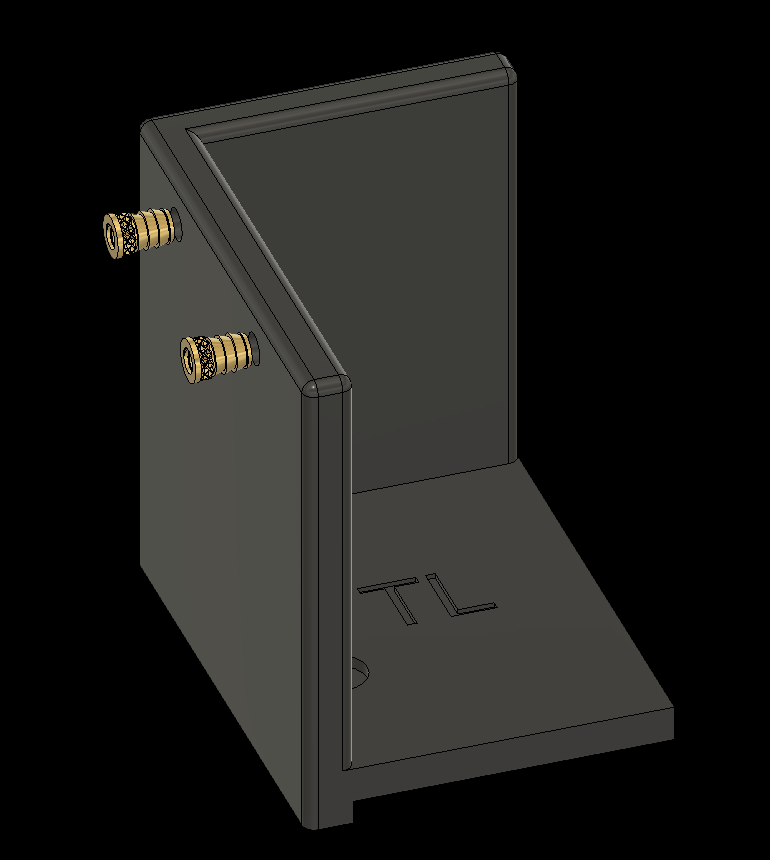
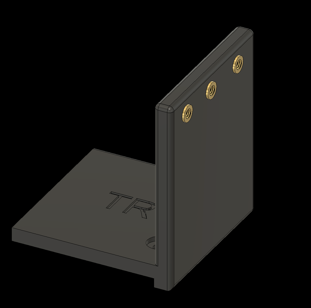
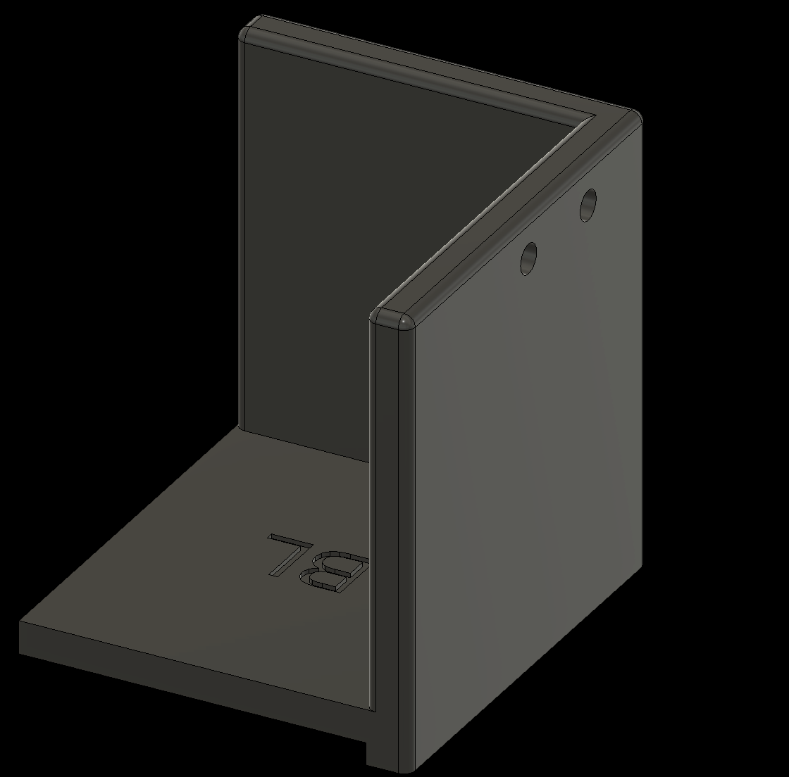
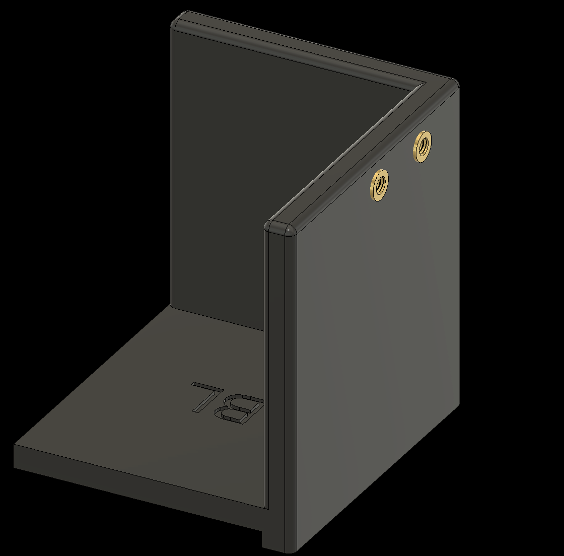
2.7 Add threaded inserts to the Corner Pieces (4x)
2.7a Top Left Corner

2. Adding Threaded Inserts to the Components
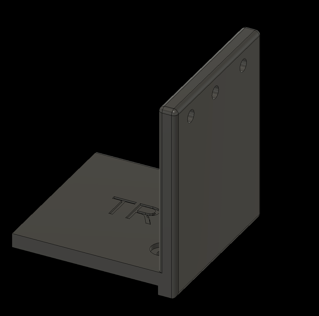
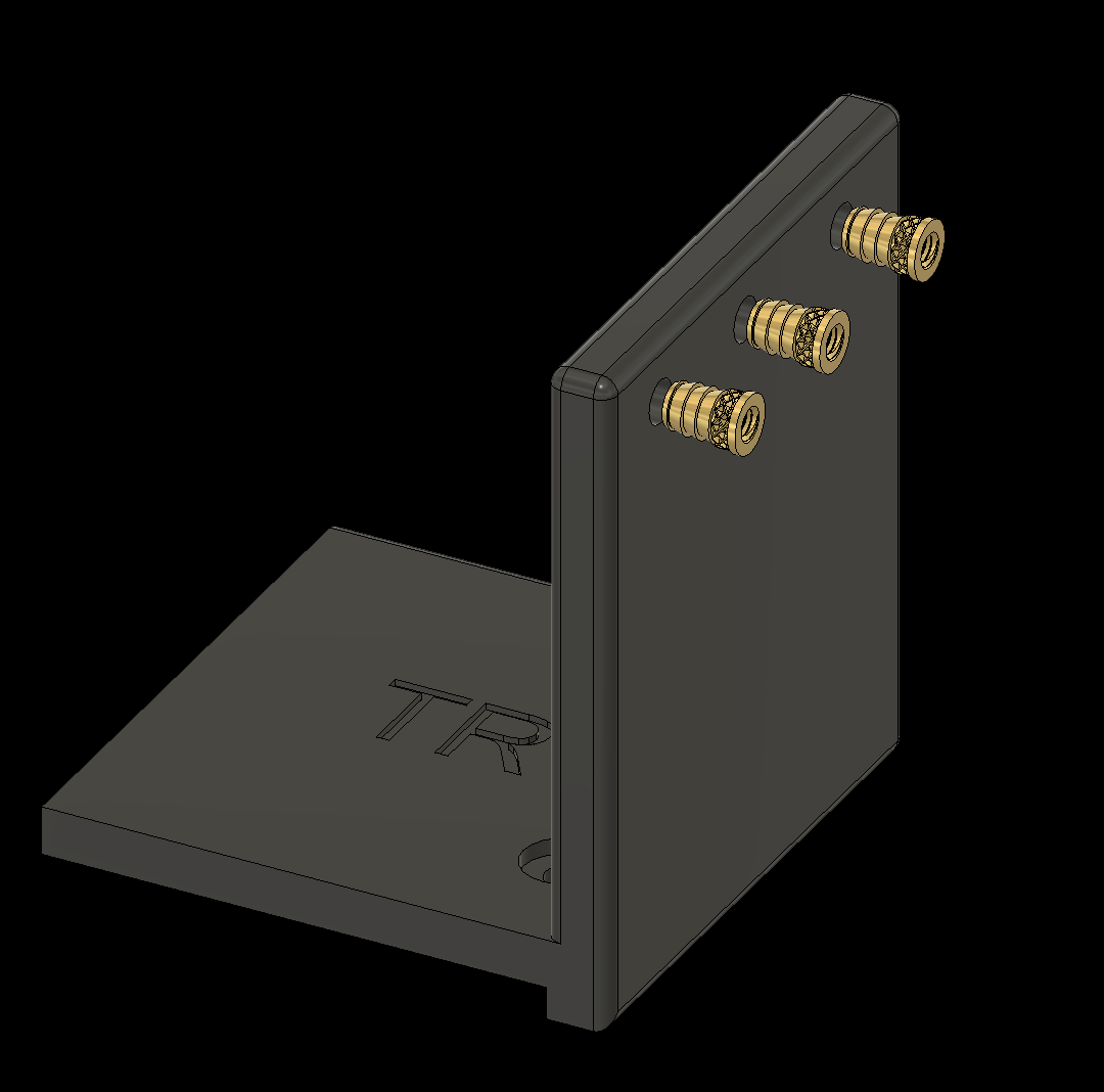
2.7 Add threaded inserts to the Corner Pieces (4x)
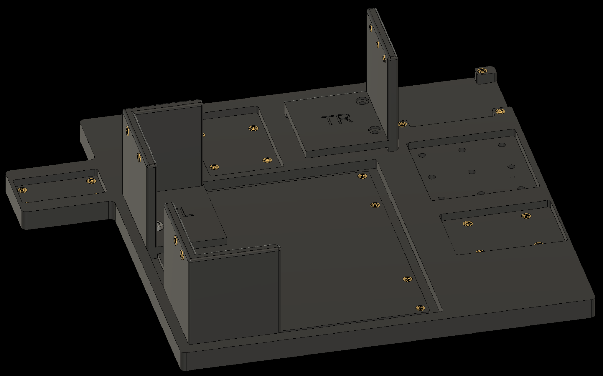
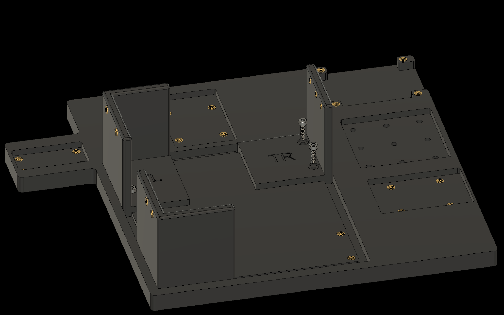
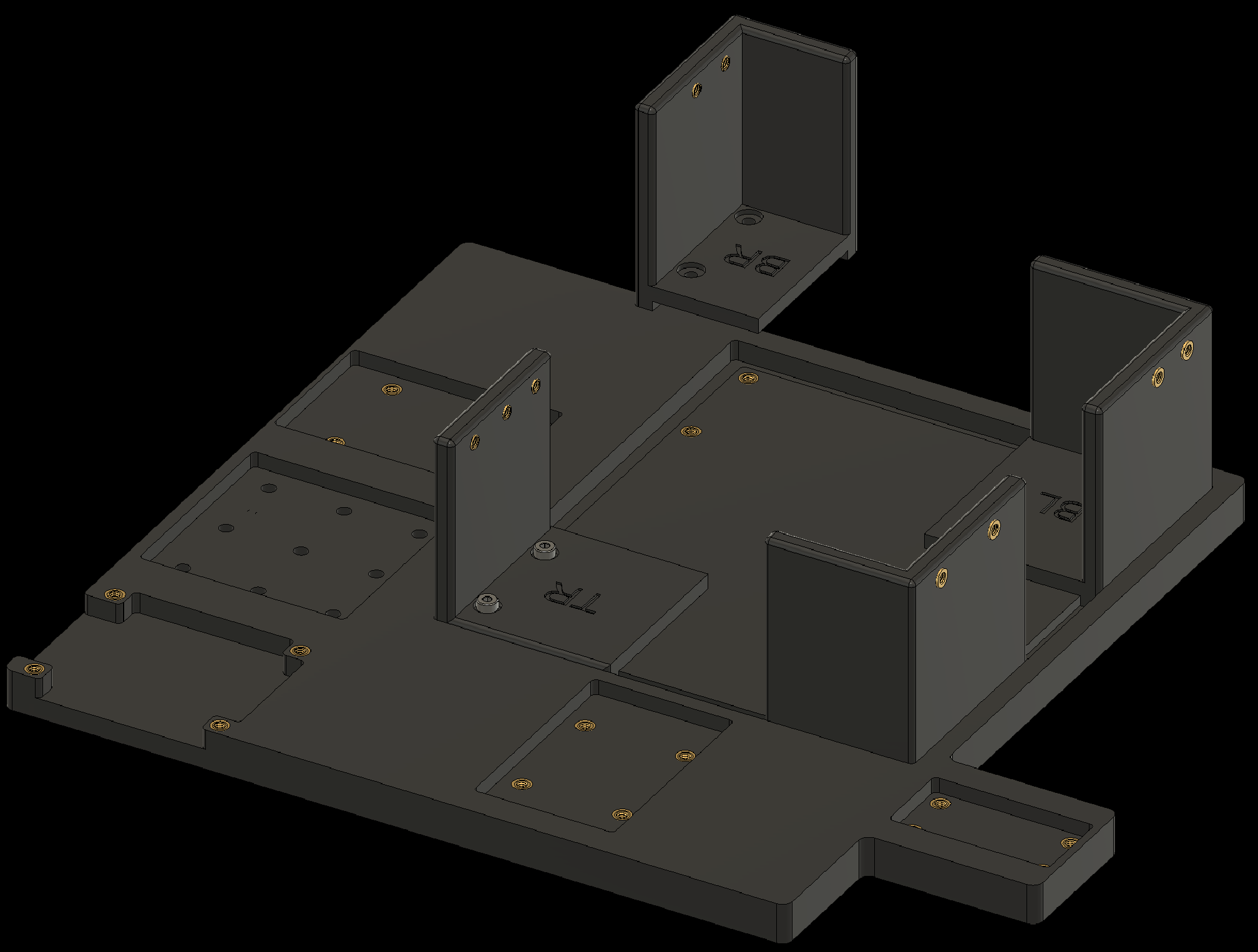
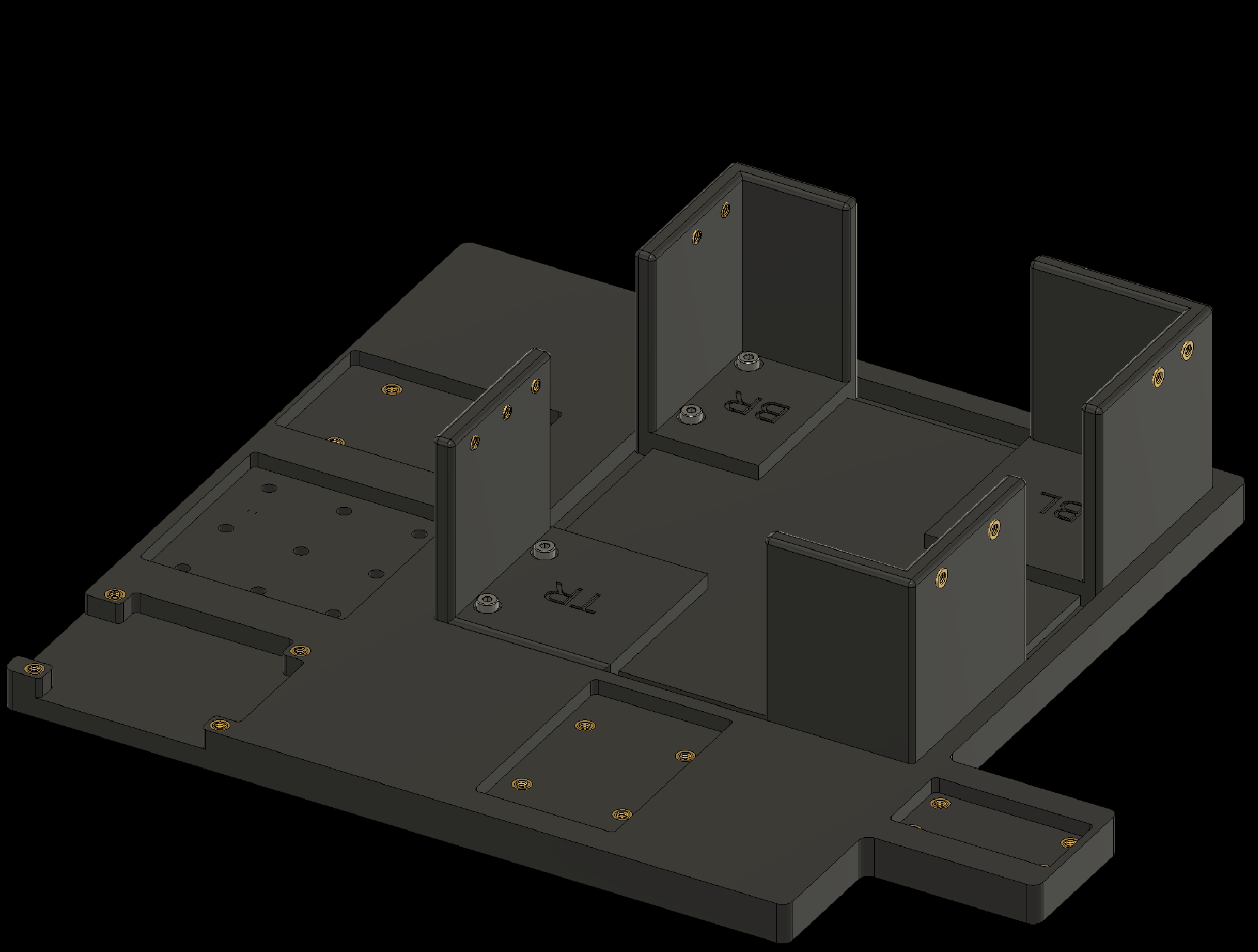
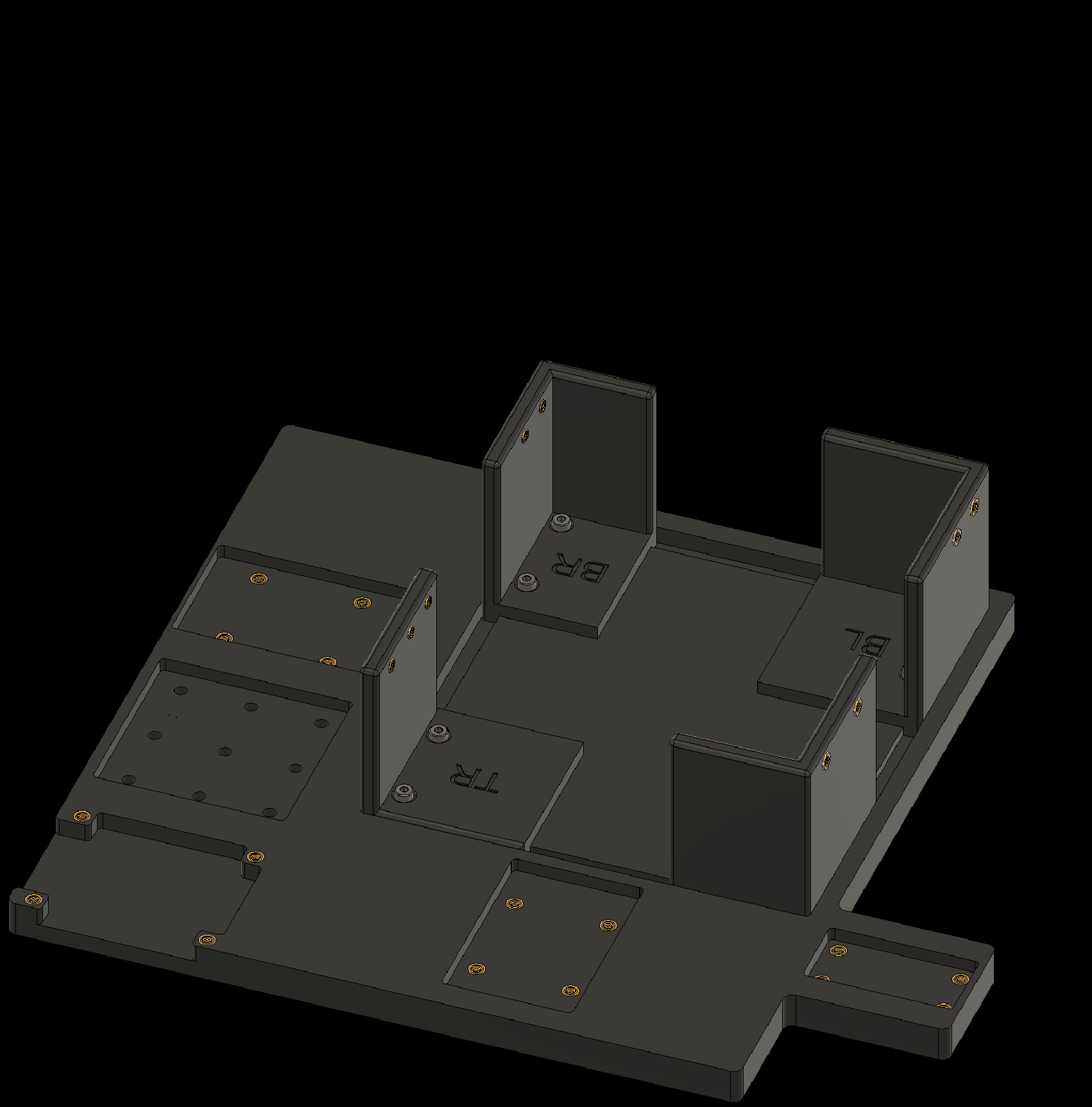
2.7b Top Right Corner
2. Adding Threaded Inserts to the Components
2.7 Add threaded inserts to the Corner Pieces (4x)
2.7c Bottom Left Corner
2. Adding Threaded Inserts to the Components
2.7 Add threaded inserts to the Corner Pieces (4x)
2.7d Bottom Right Corner
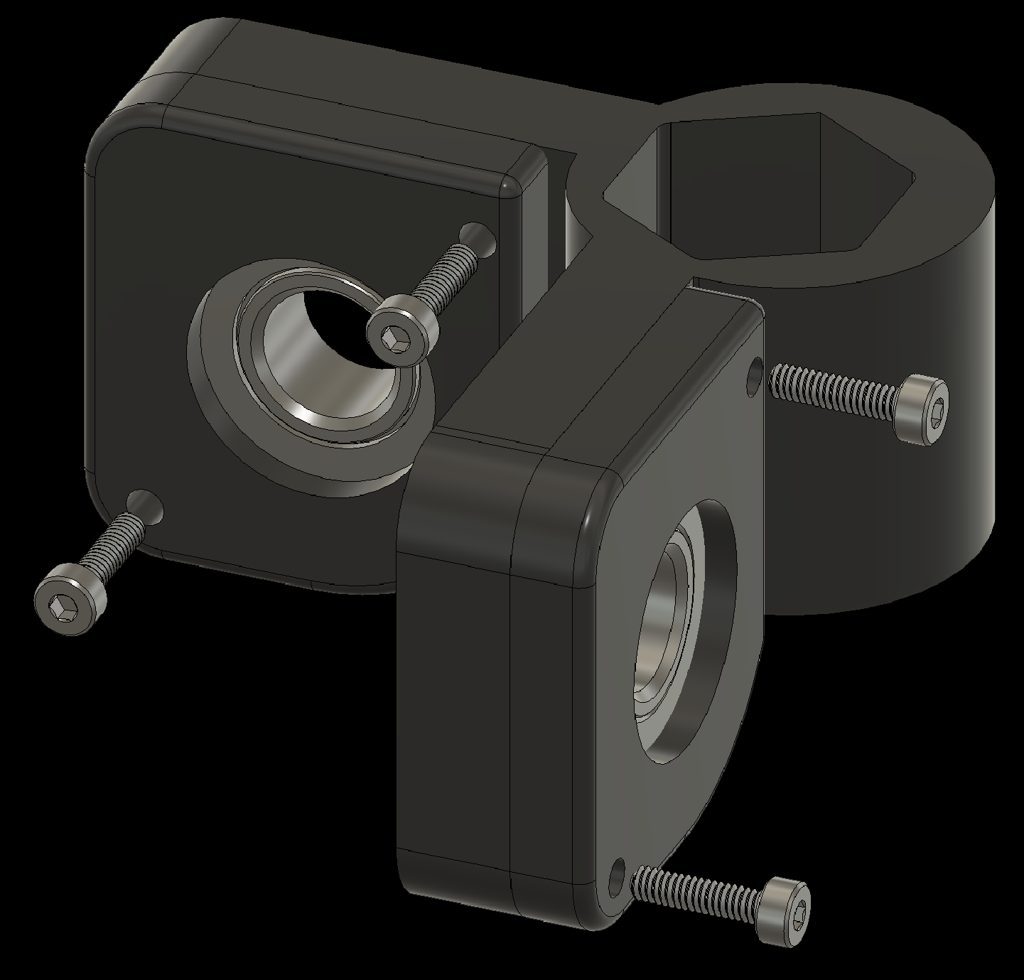
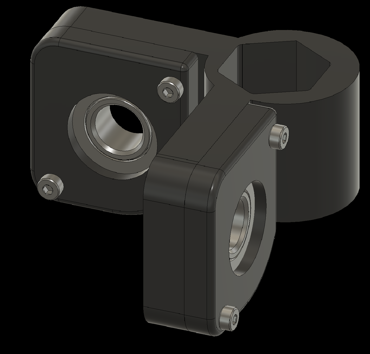
3. Assembling Individual Components
Next, assemble the individual components. The following slides show each step. Apply a thread-locking compound to all screws so they do not loosen over time—Loctite 243 Threadlocker works well.
If you are using the replacement metal horn for the Dynamixel servos, attach them to the motors before continuing.
3. Assembling Individual Components
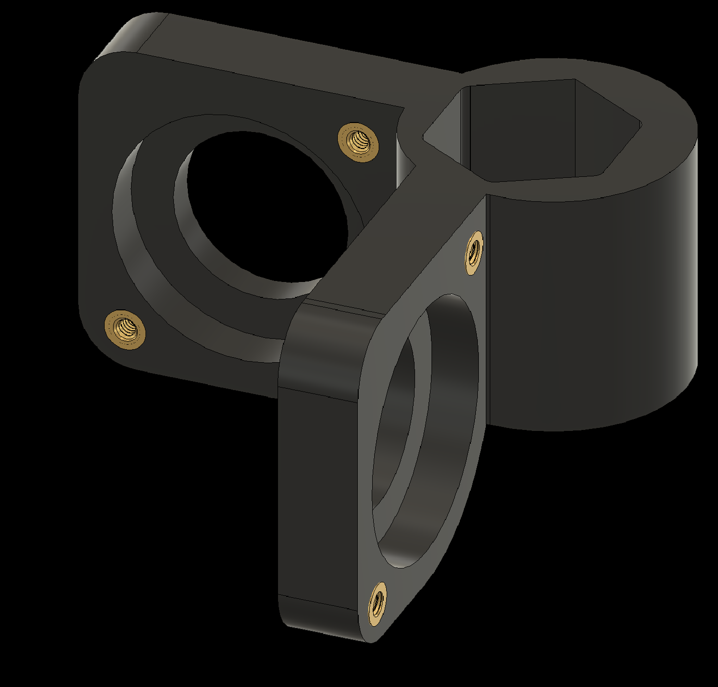
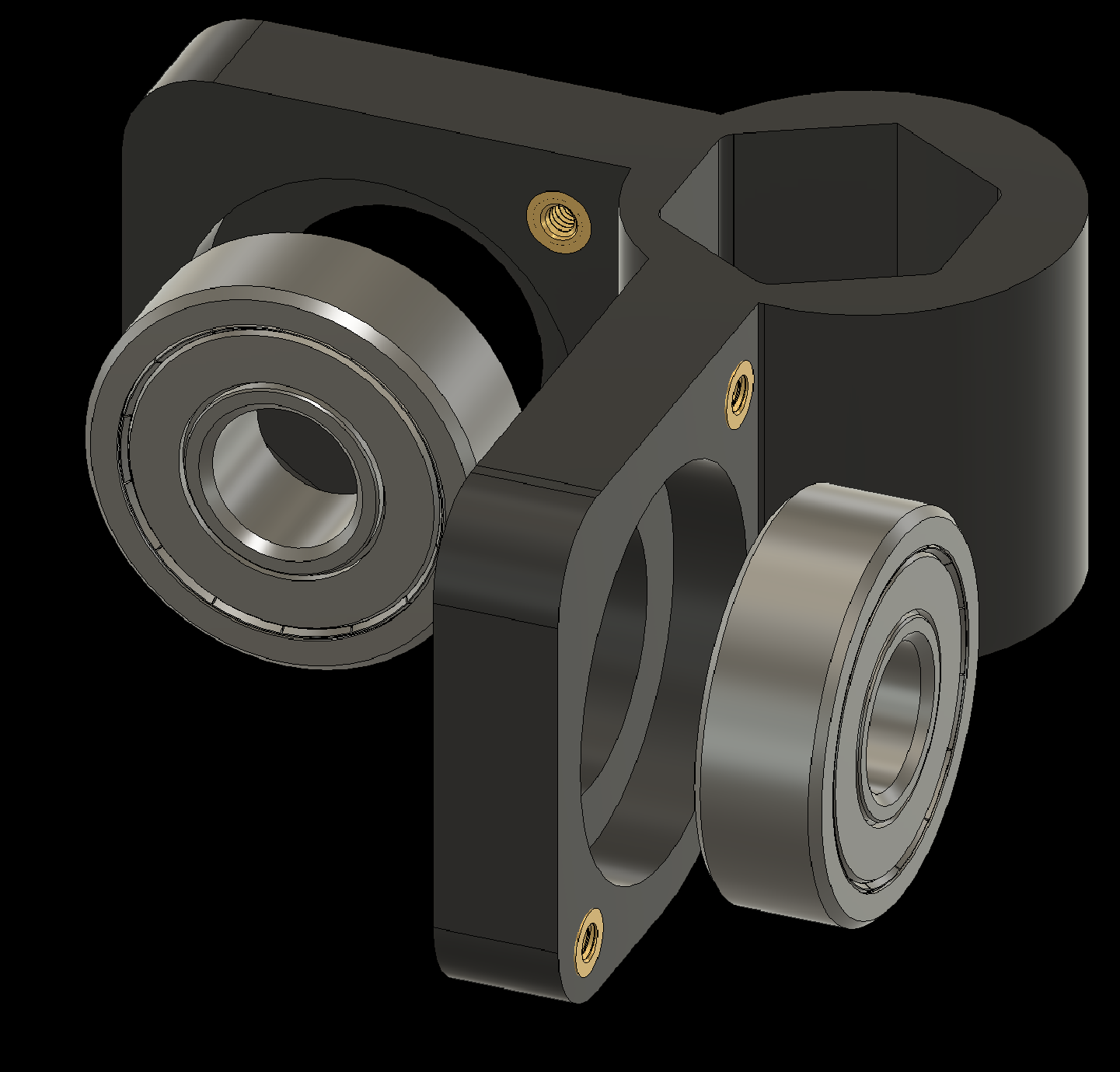
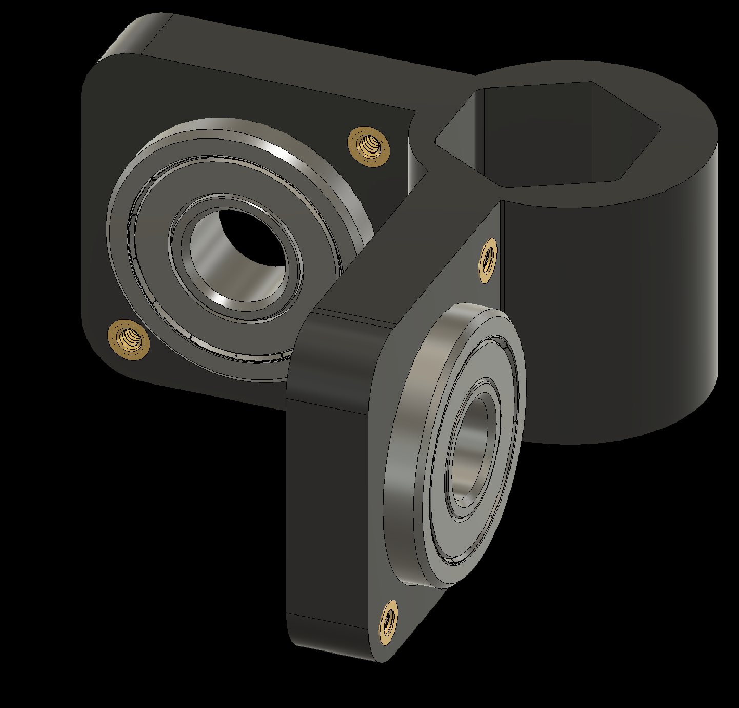
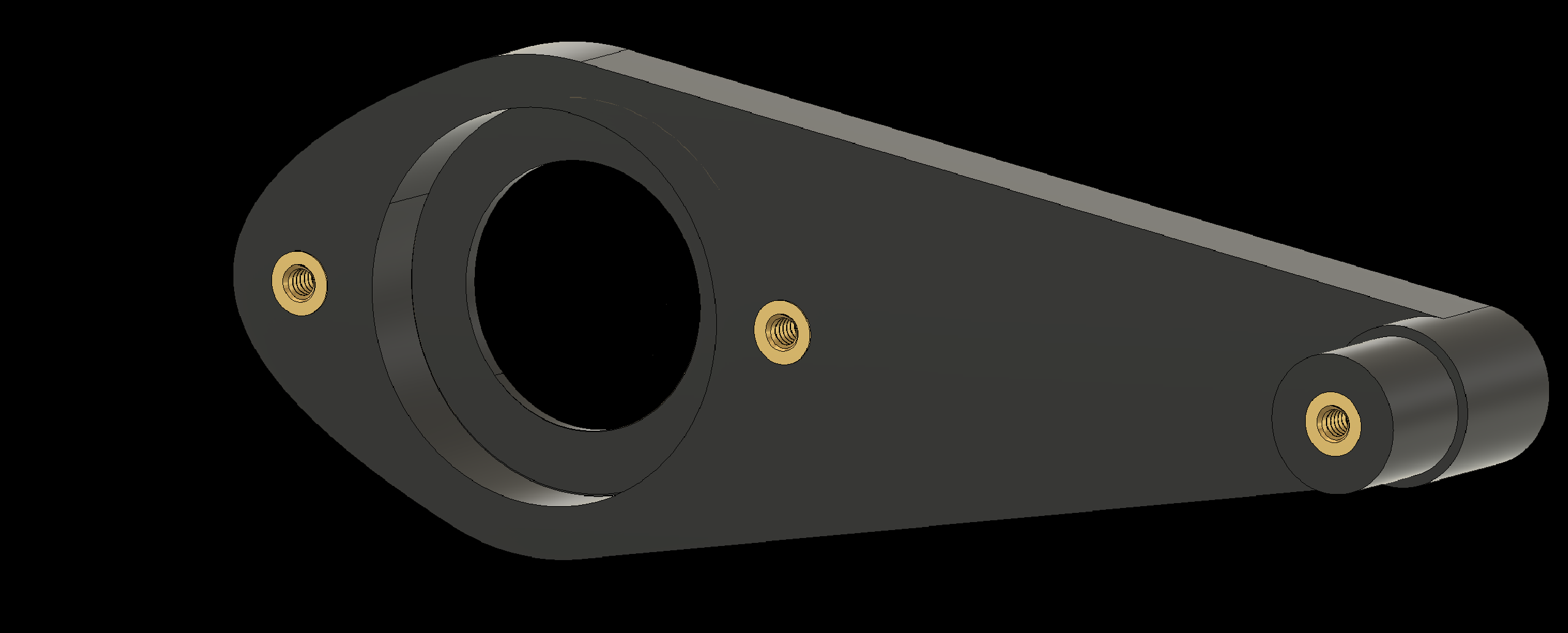
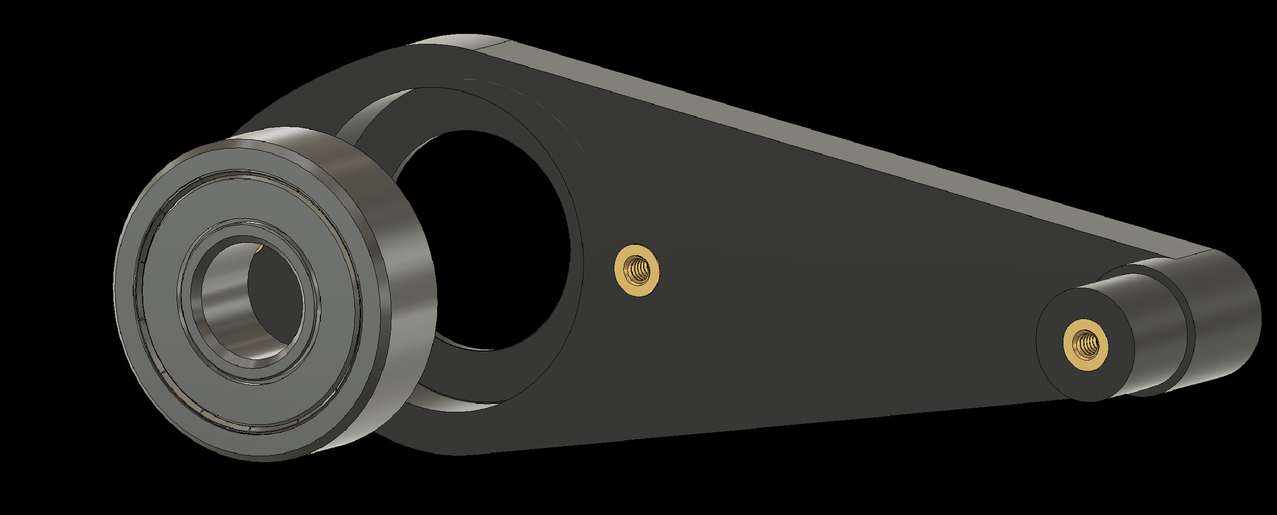
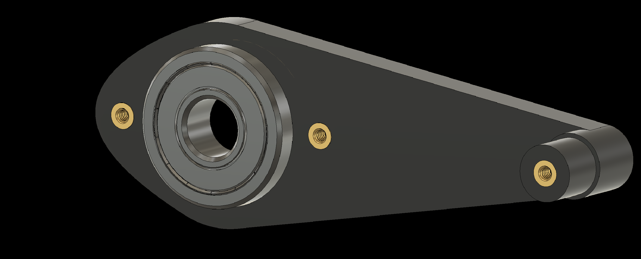
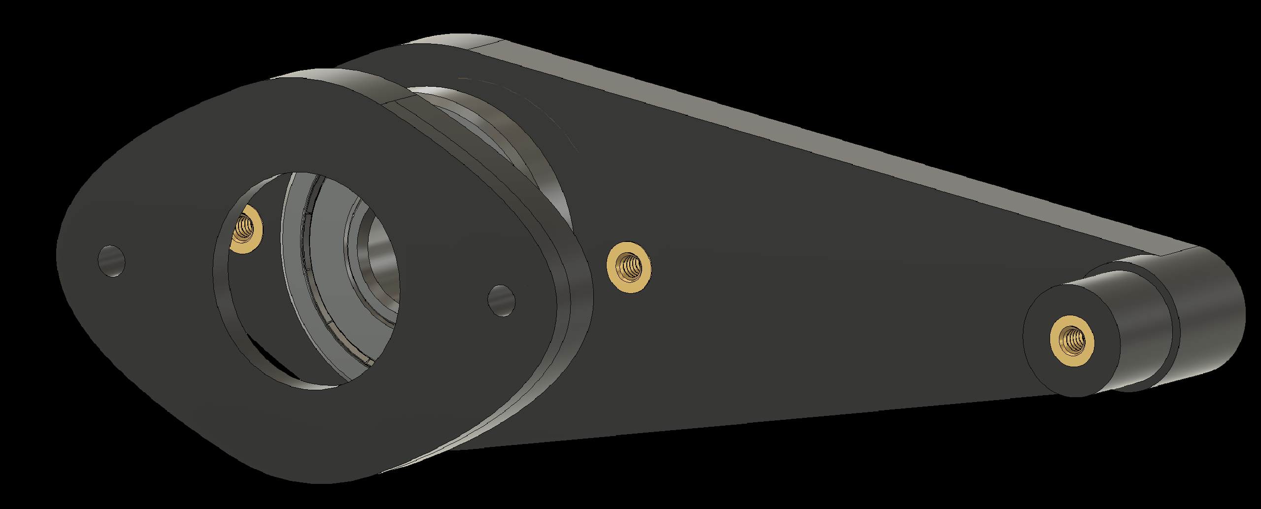
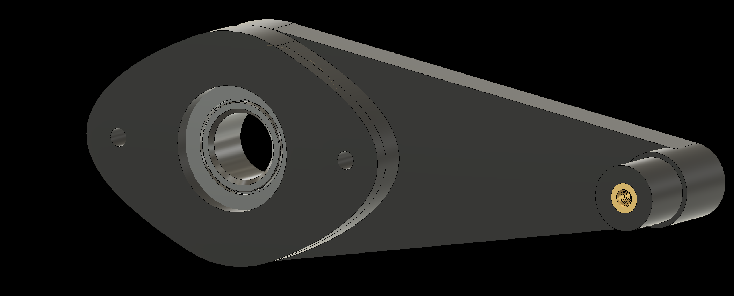
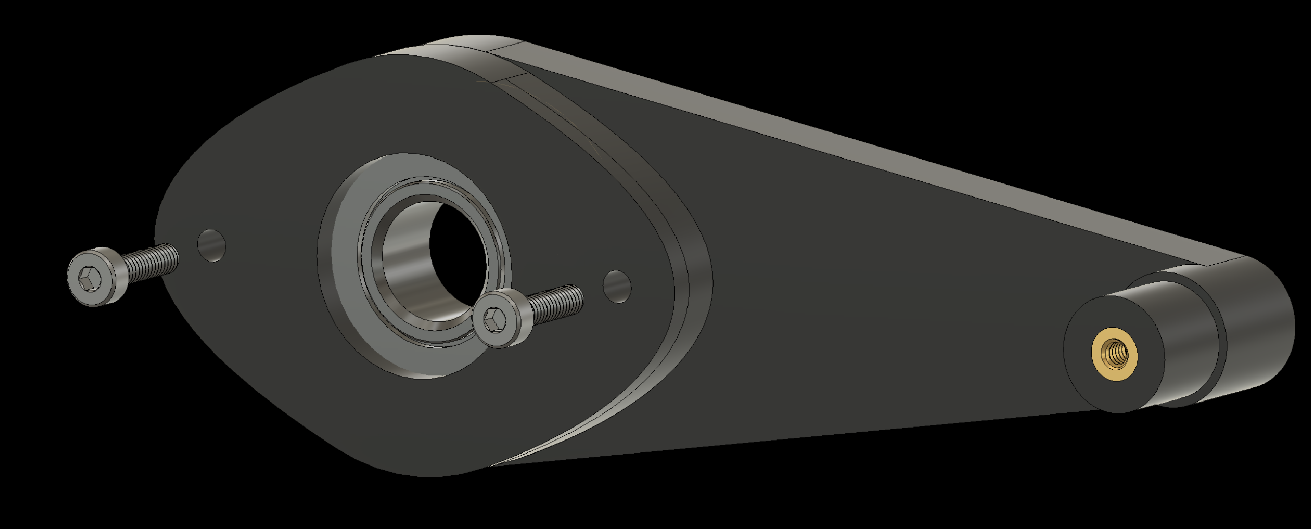
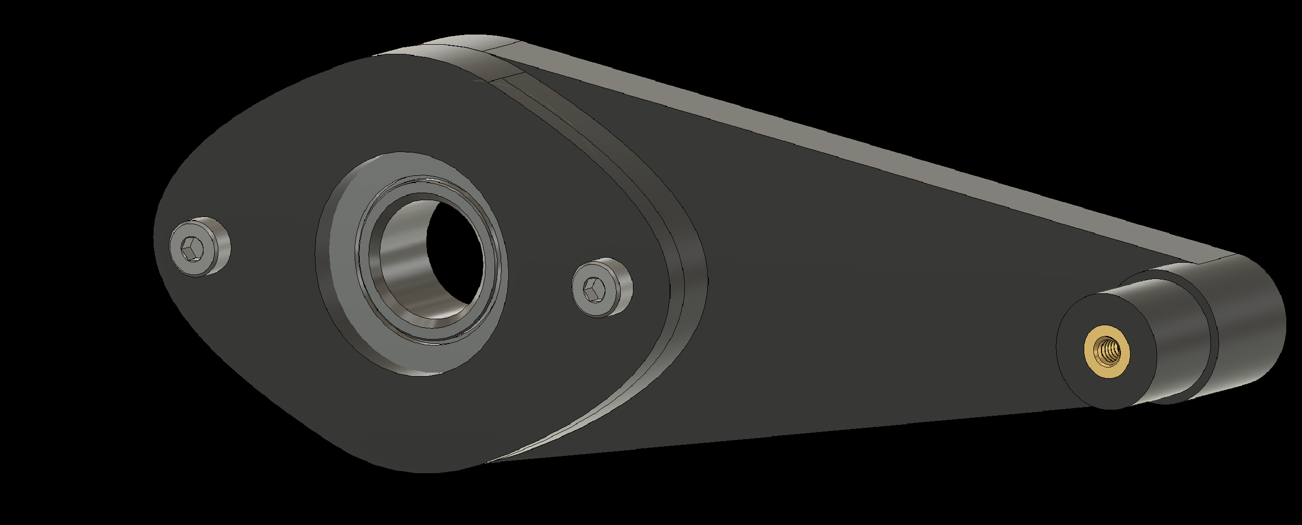
3.1 Add bearings to the Shoulders (2x)
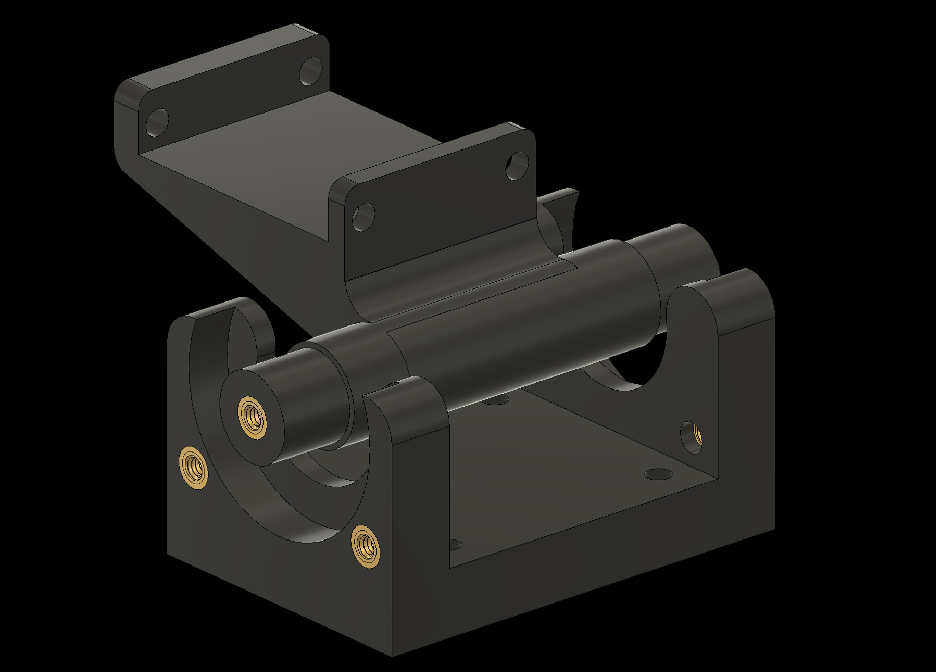
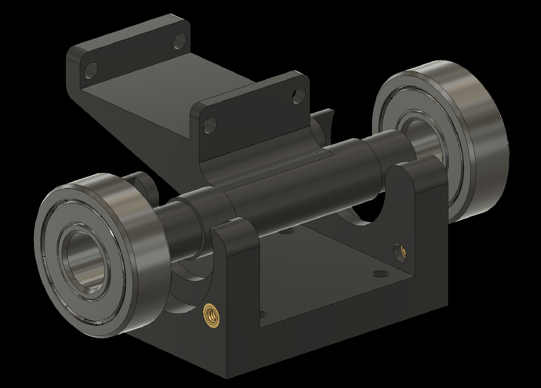
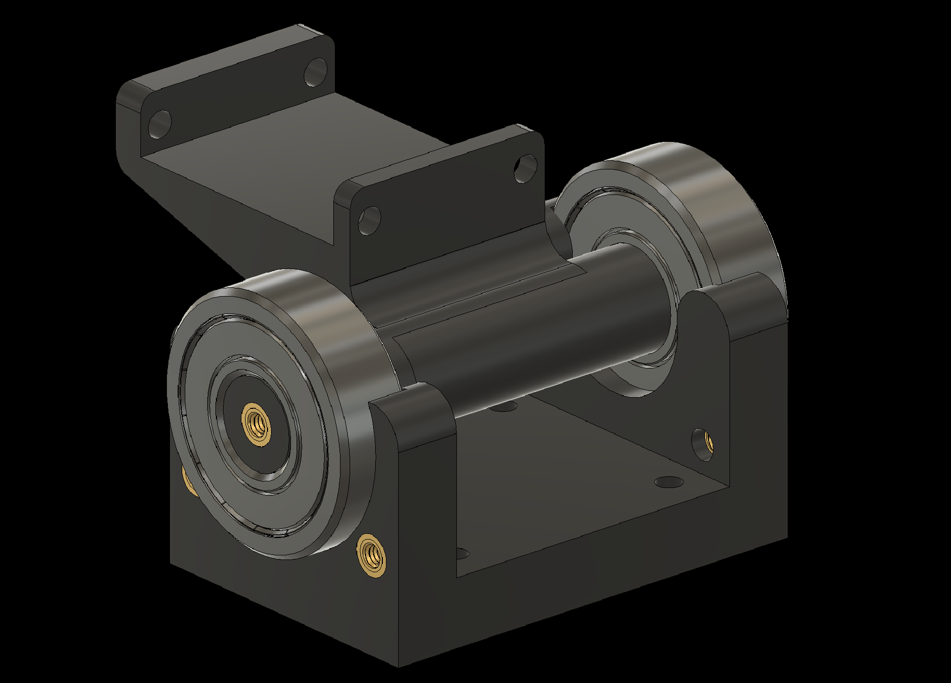
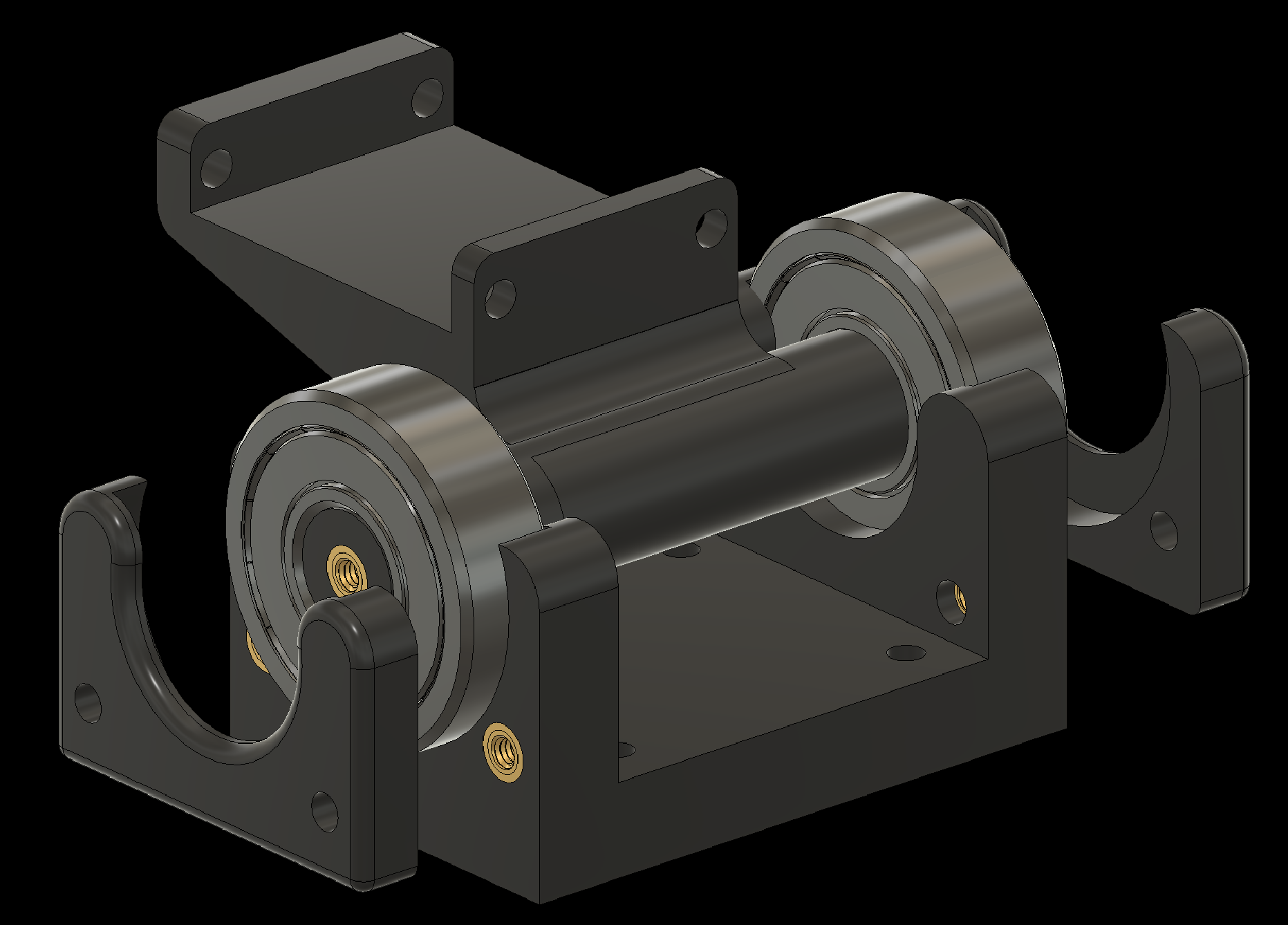
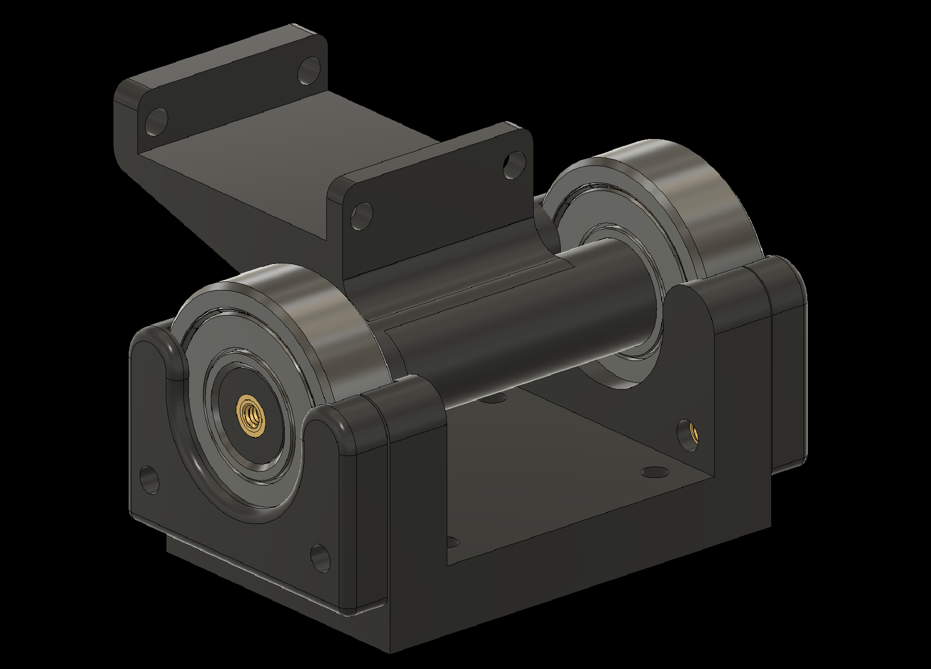
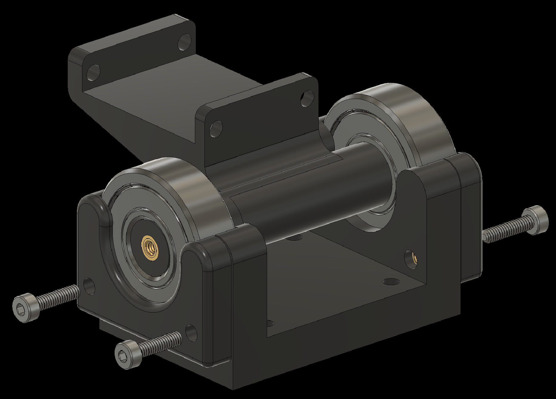
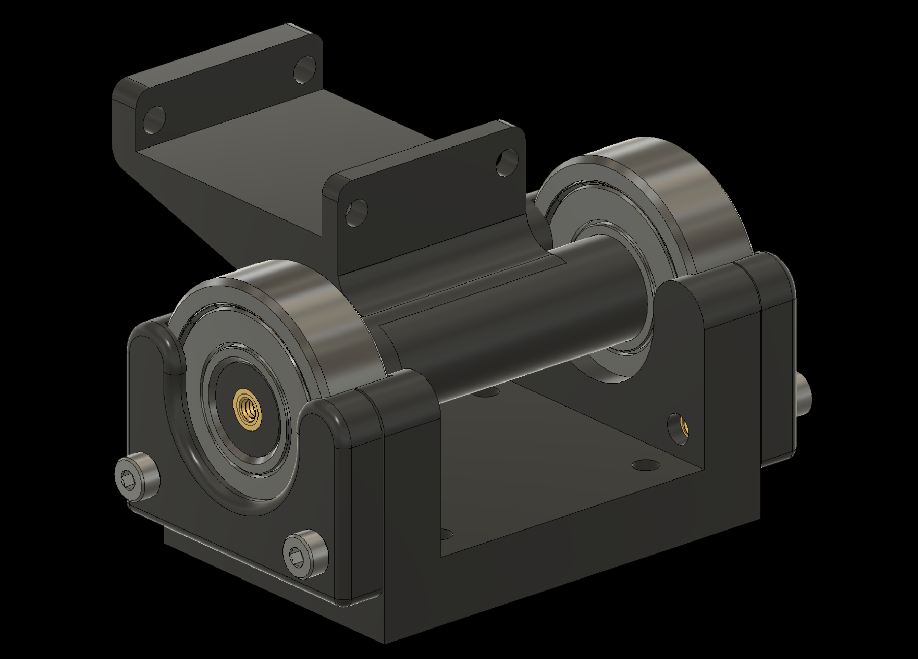
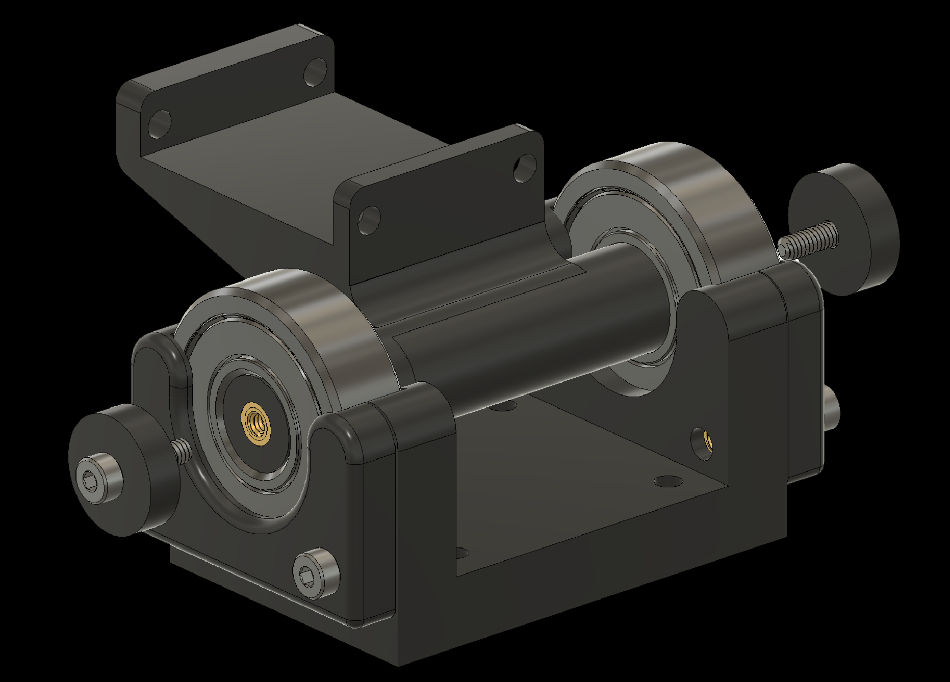
3. Assembling Individual Components
3.2 Add bearings to the Joystick Attachment
3. Assembling Individual Components
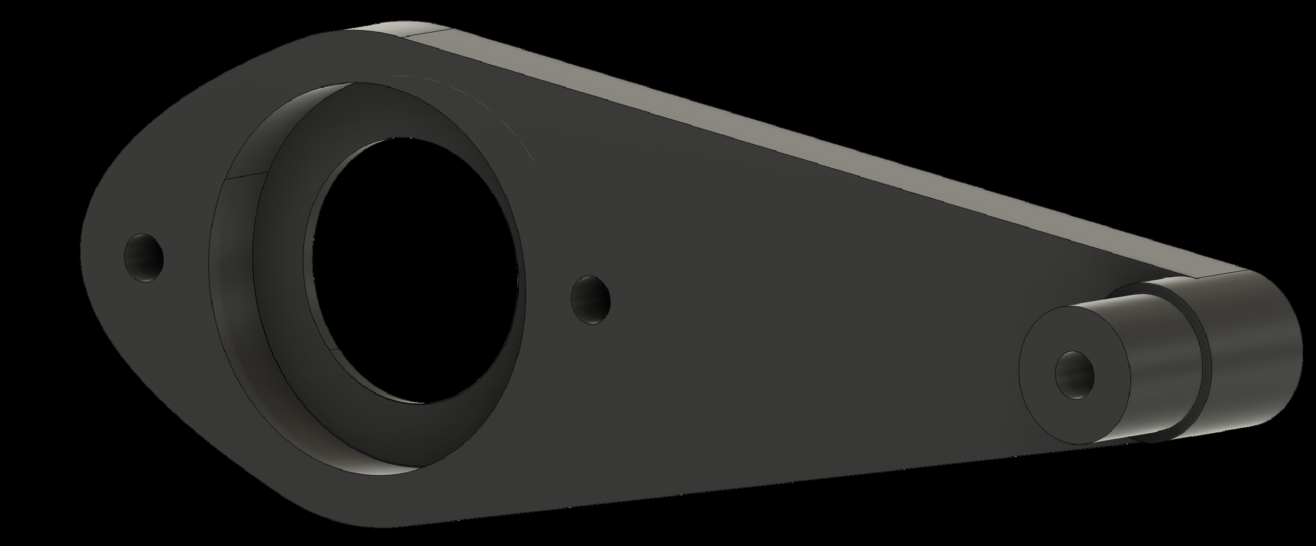
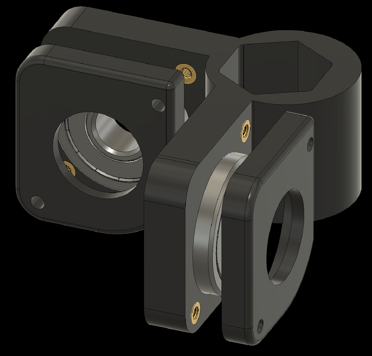
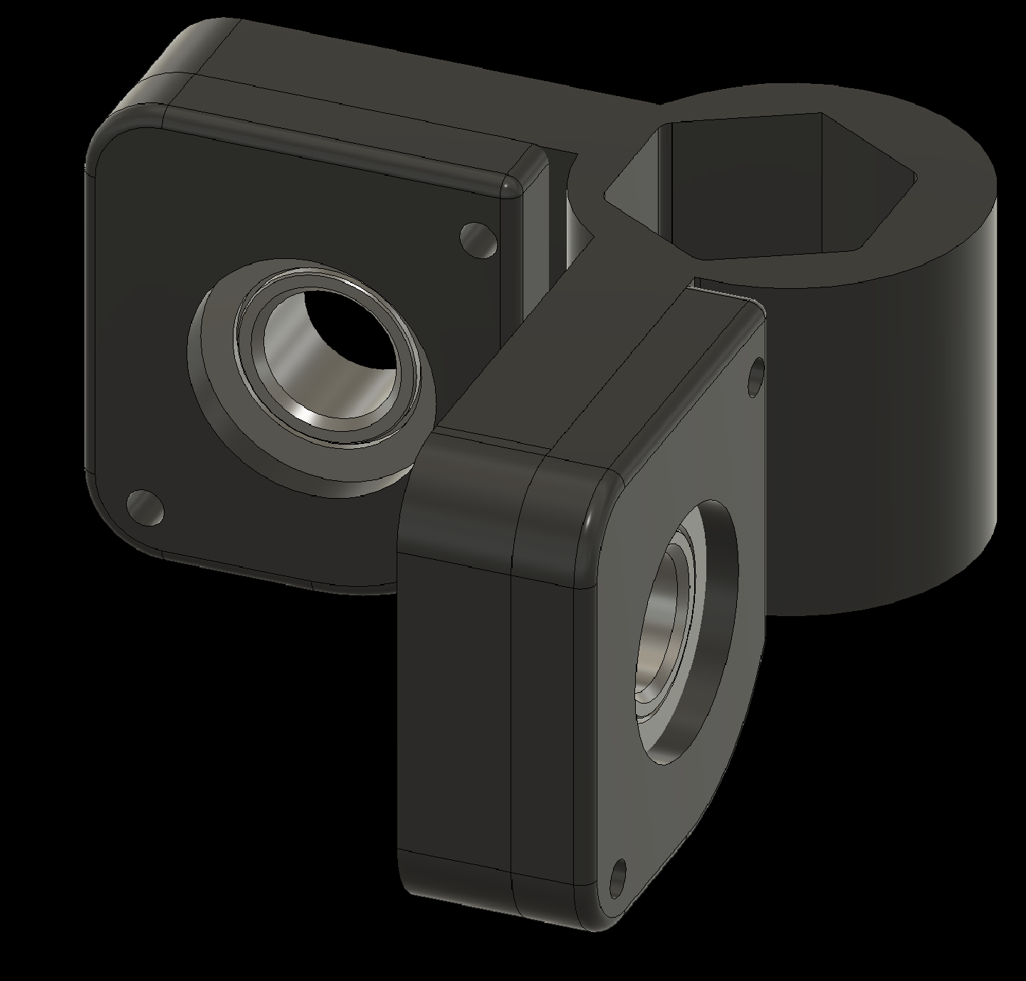
3.3 Add bearings to the Elbow-to-Finger components (2x)
3. Assembling Individual Components
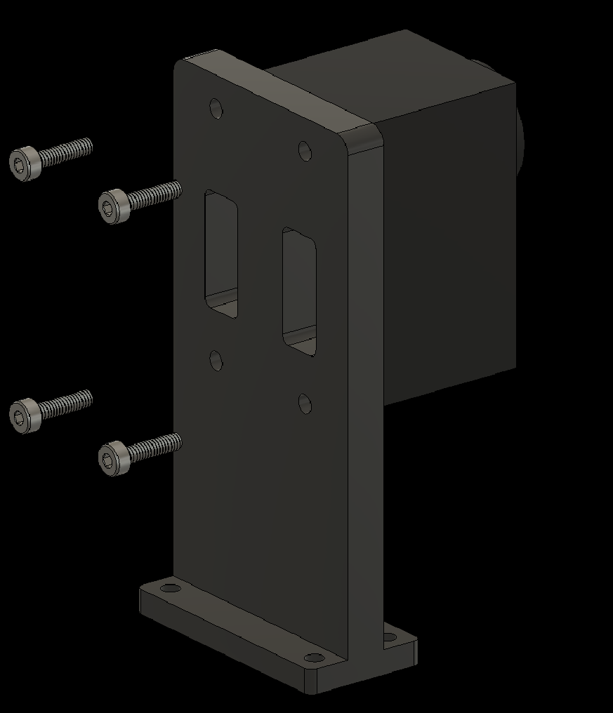
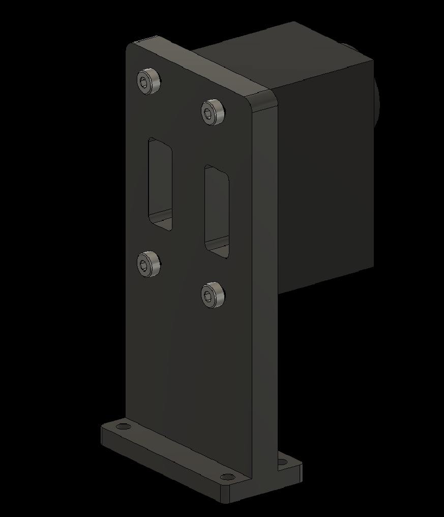
3.4 Attach the Dynamixels (2x)
3. Assembling Individual Components
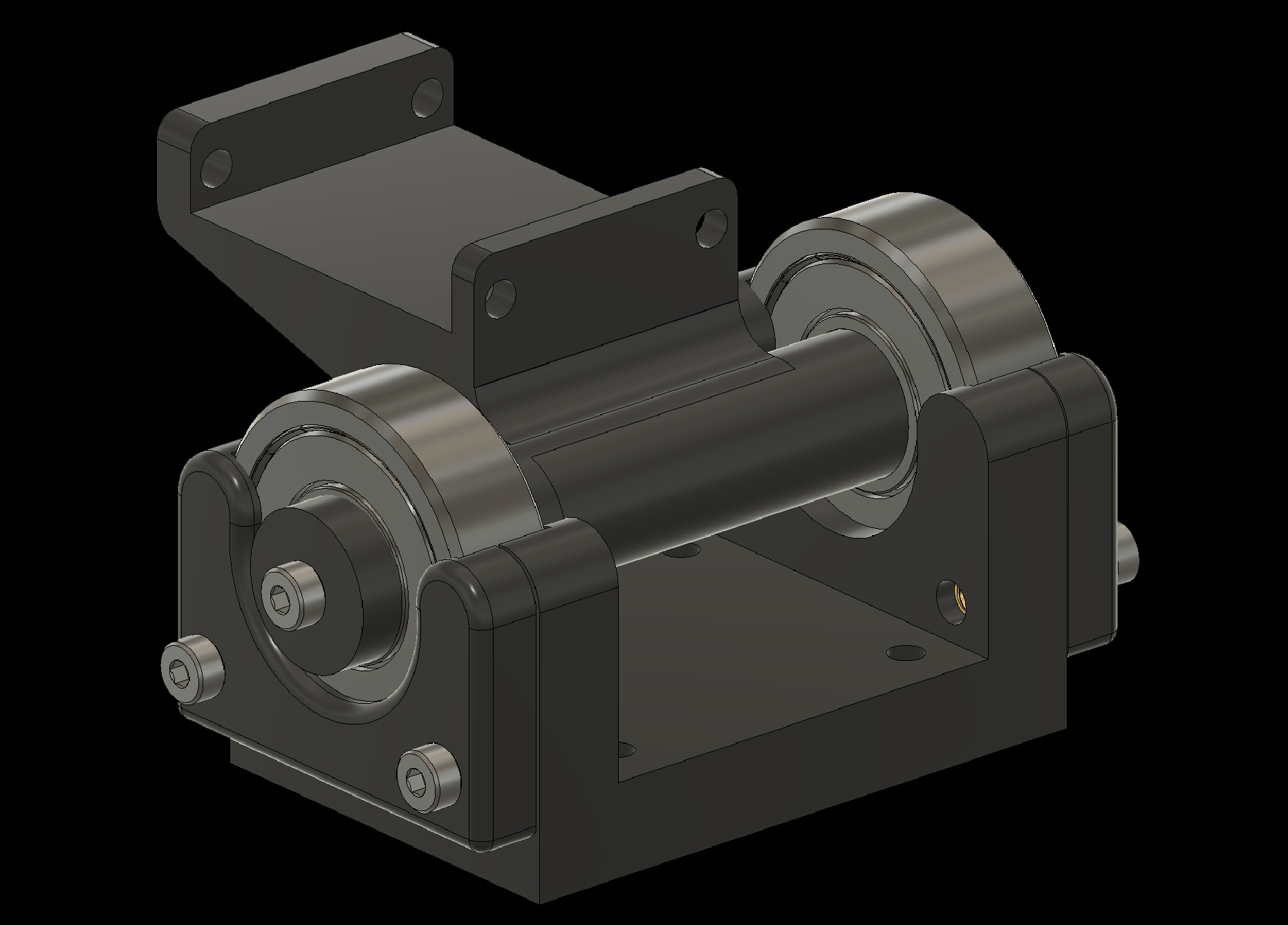
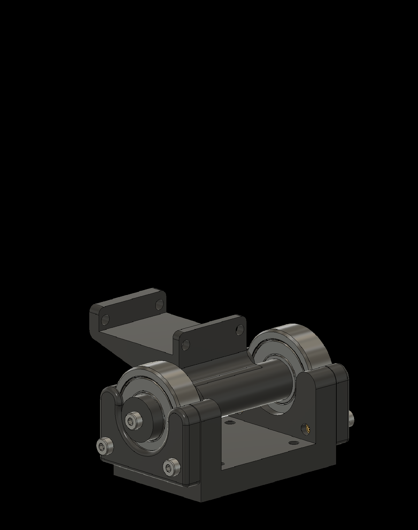
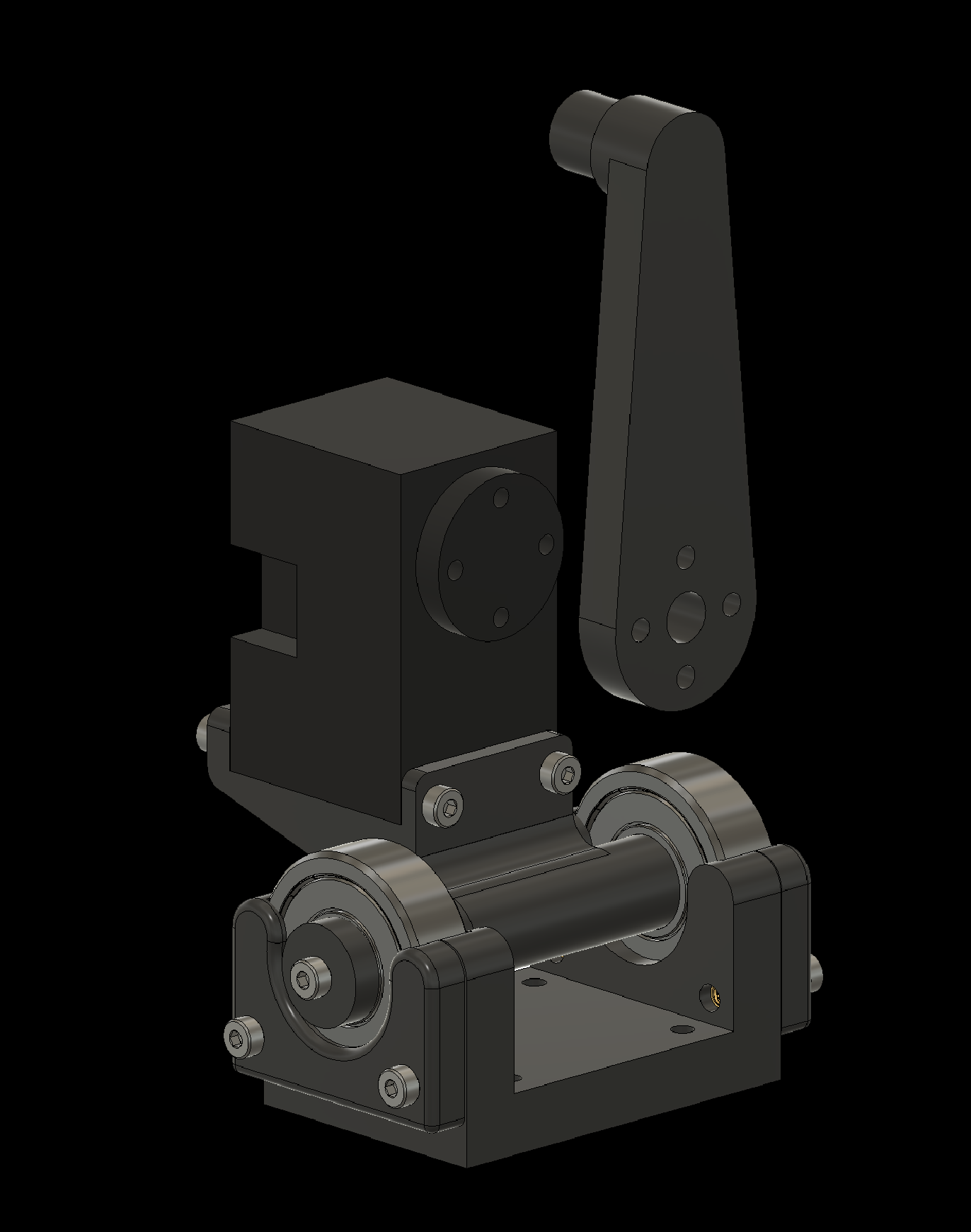
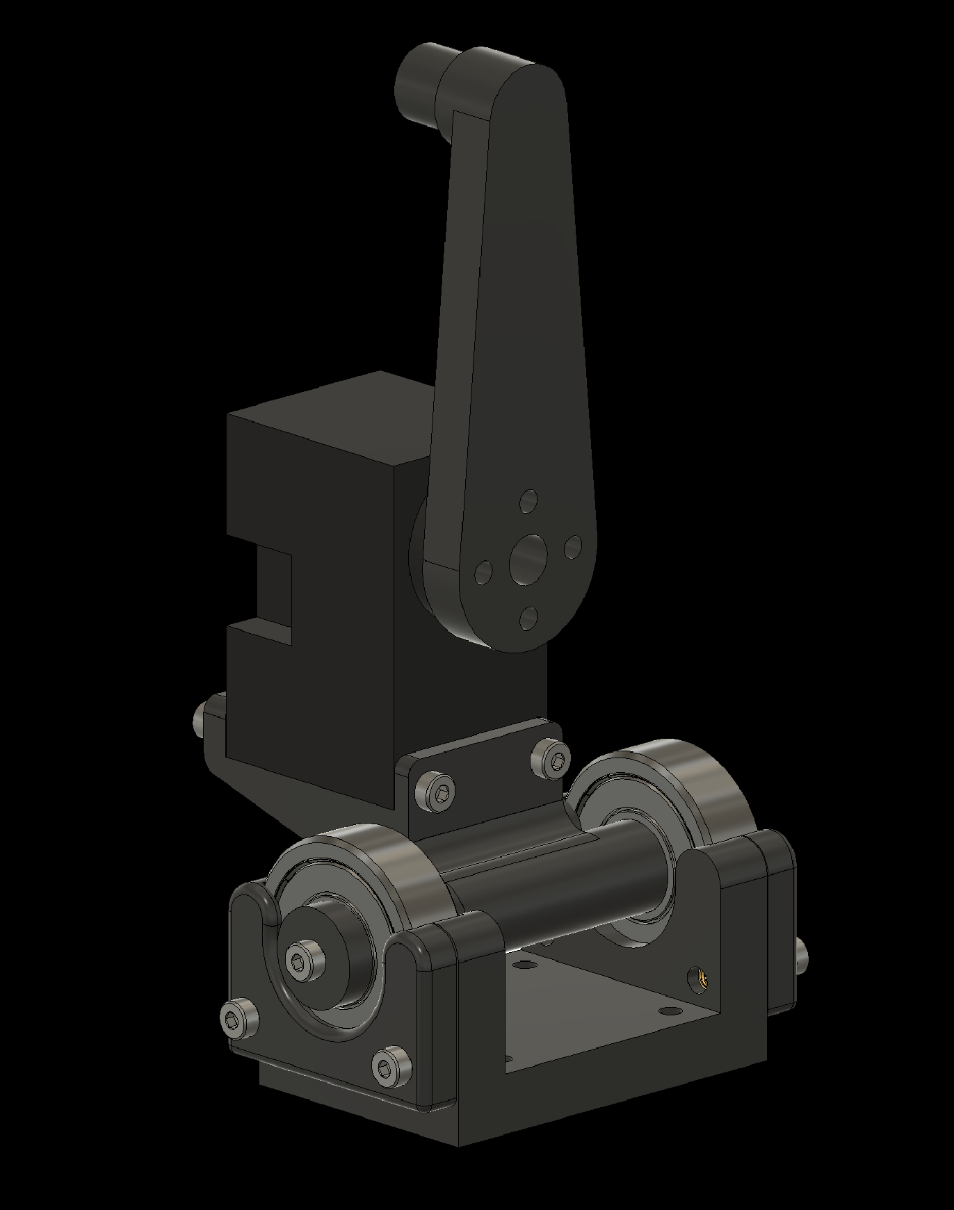
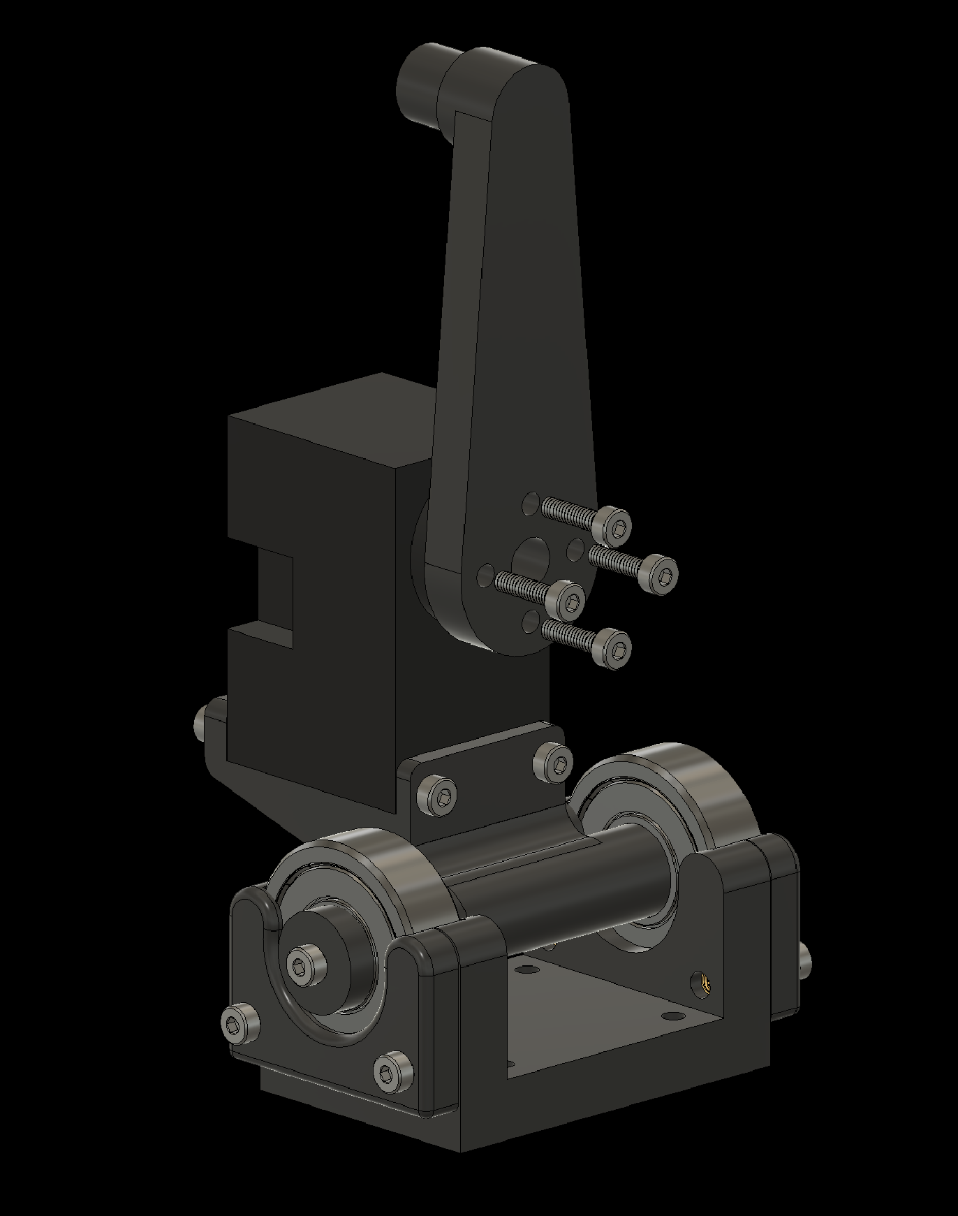
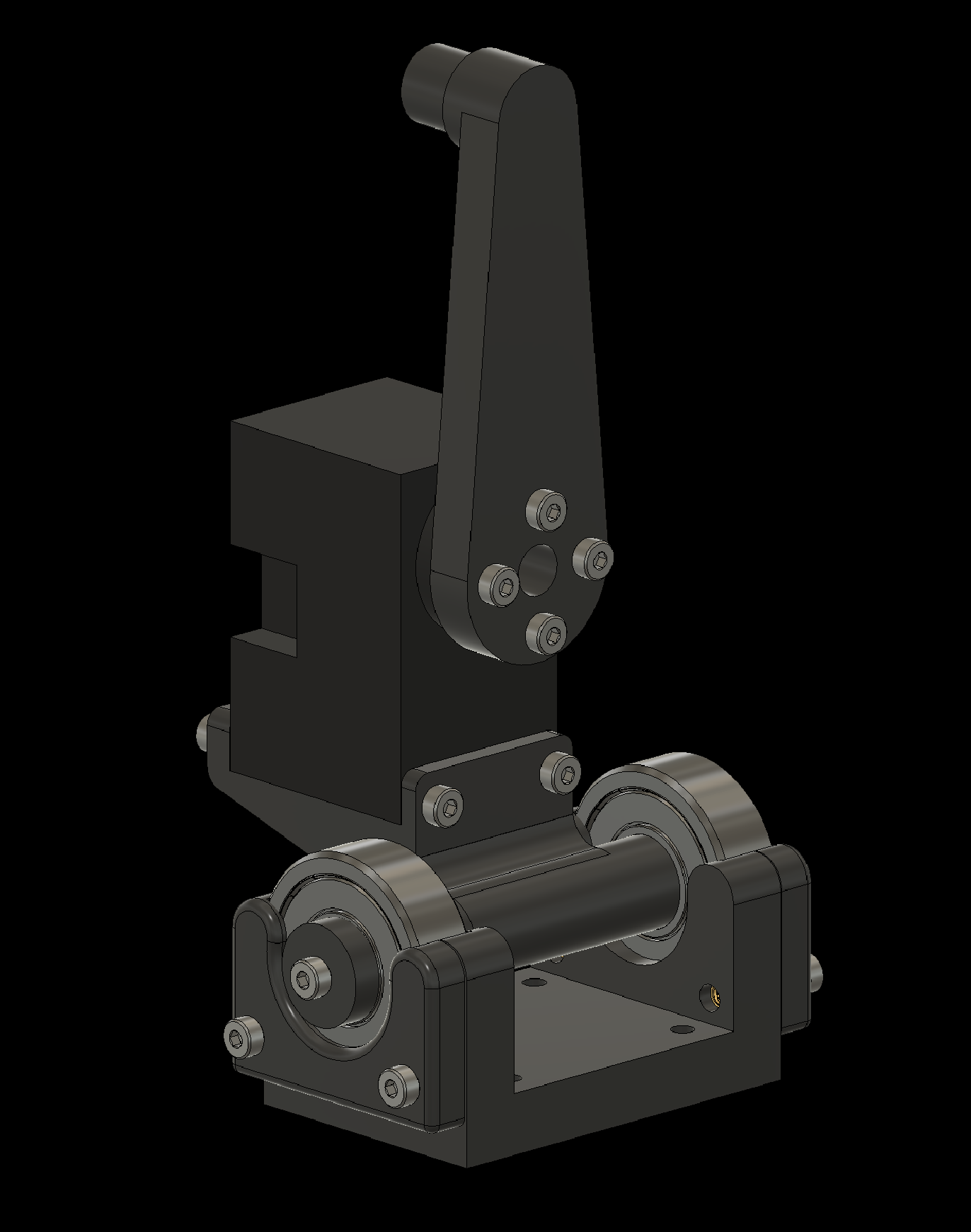
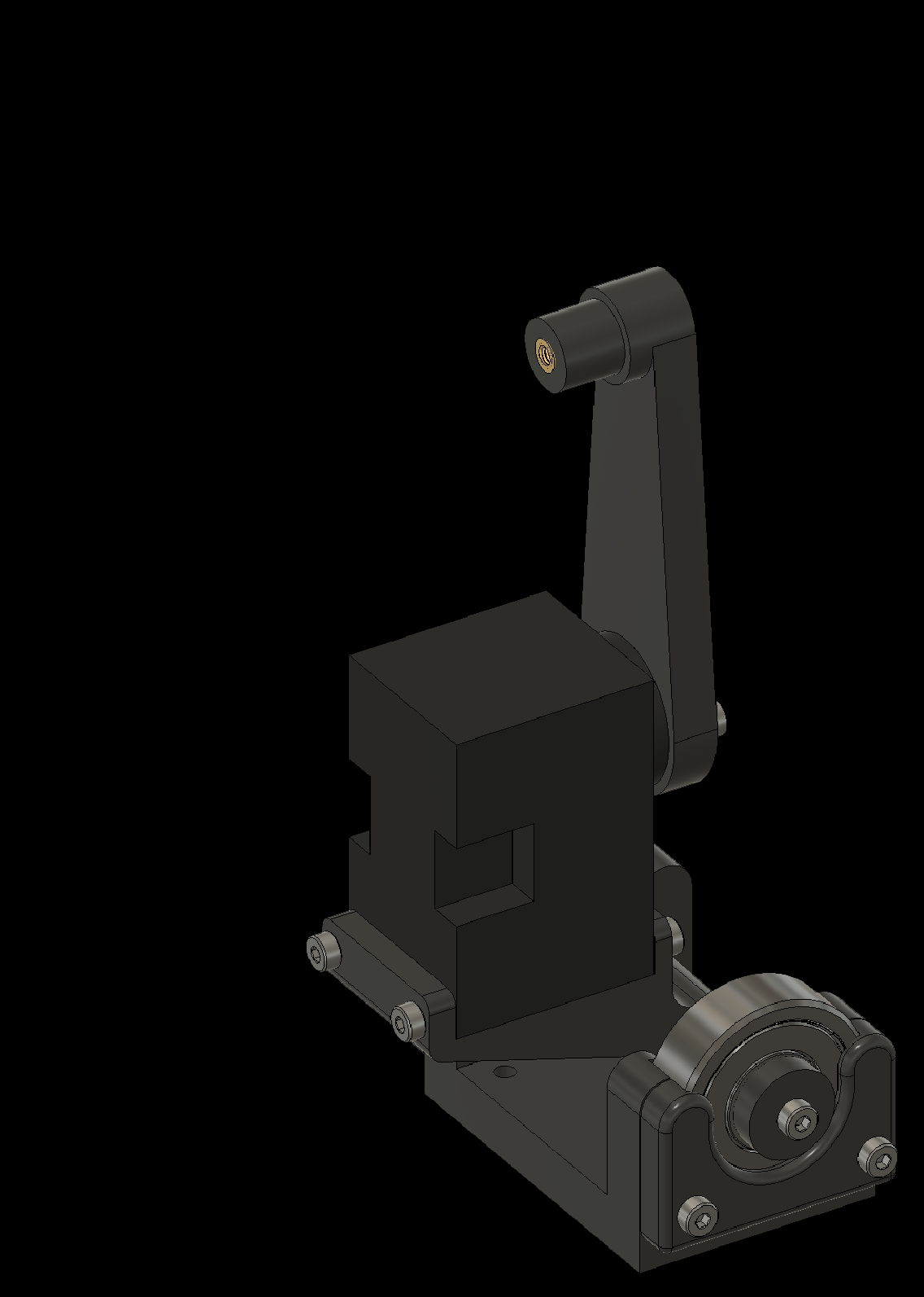
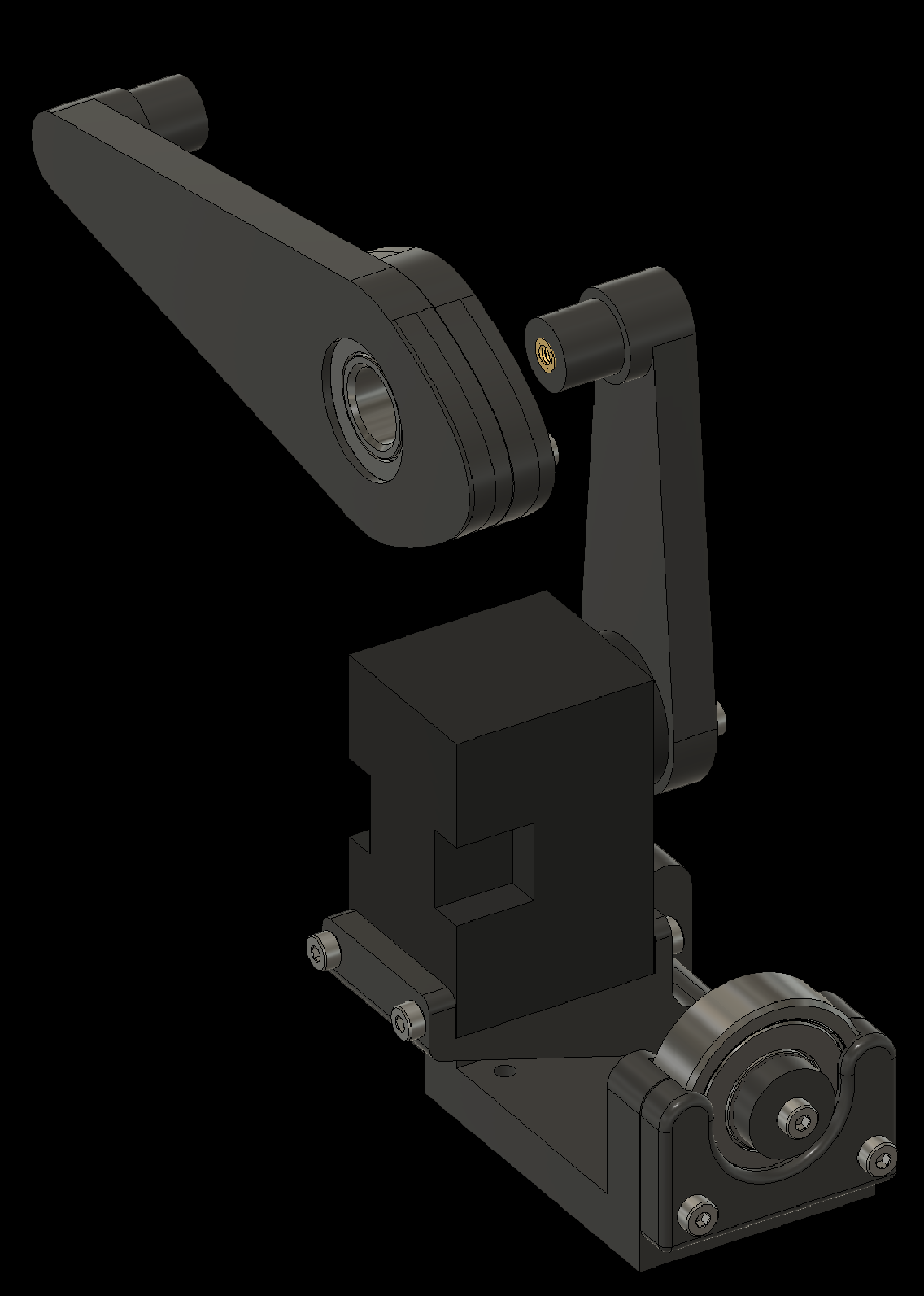
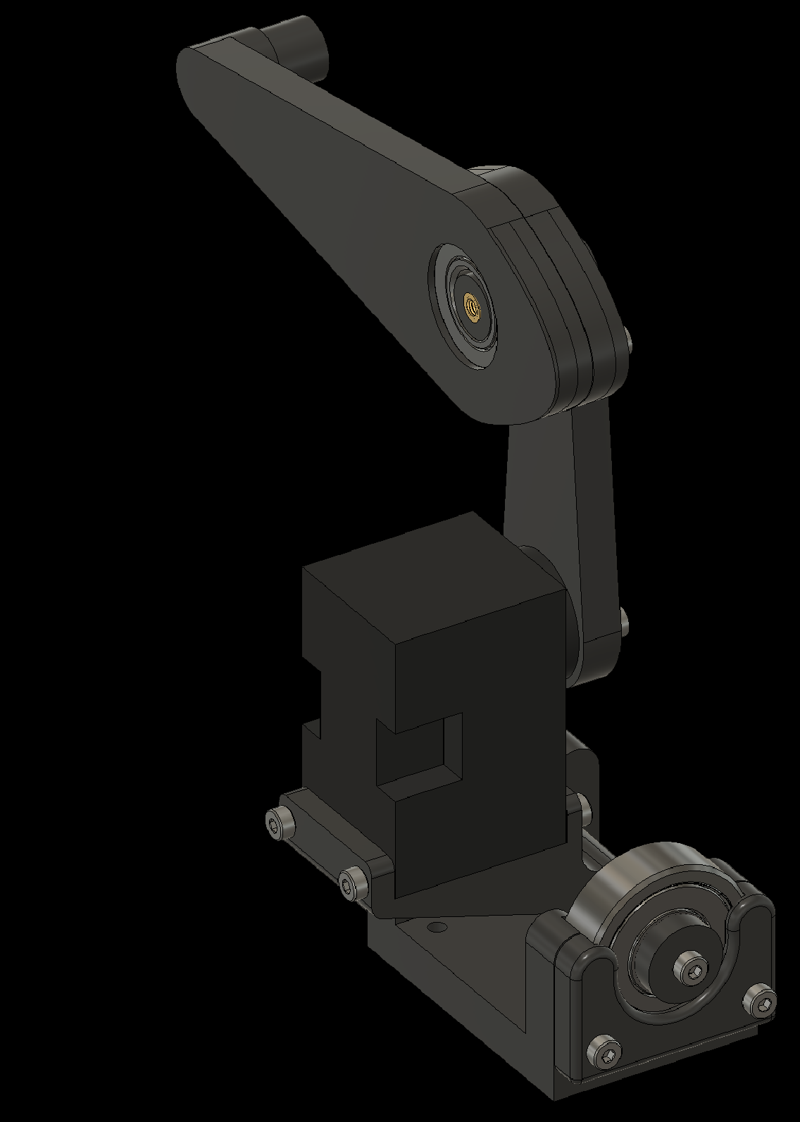
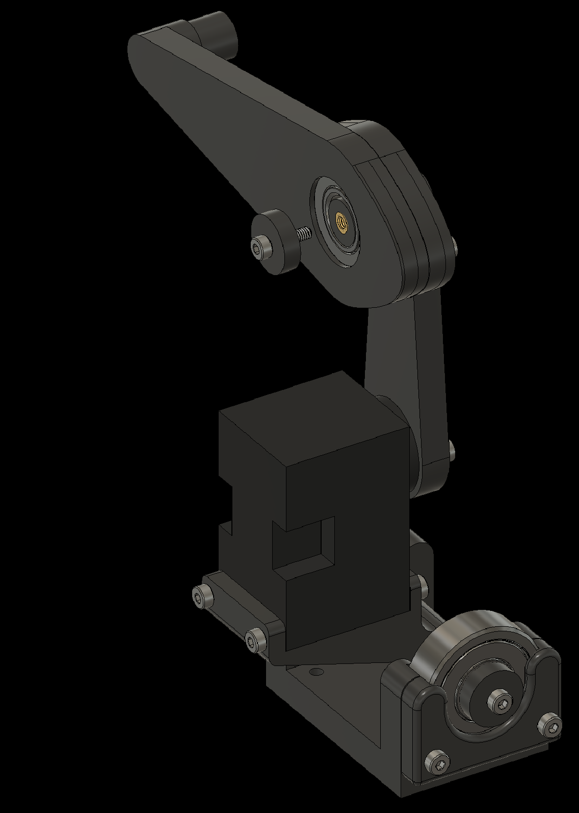
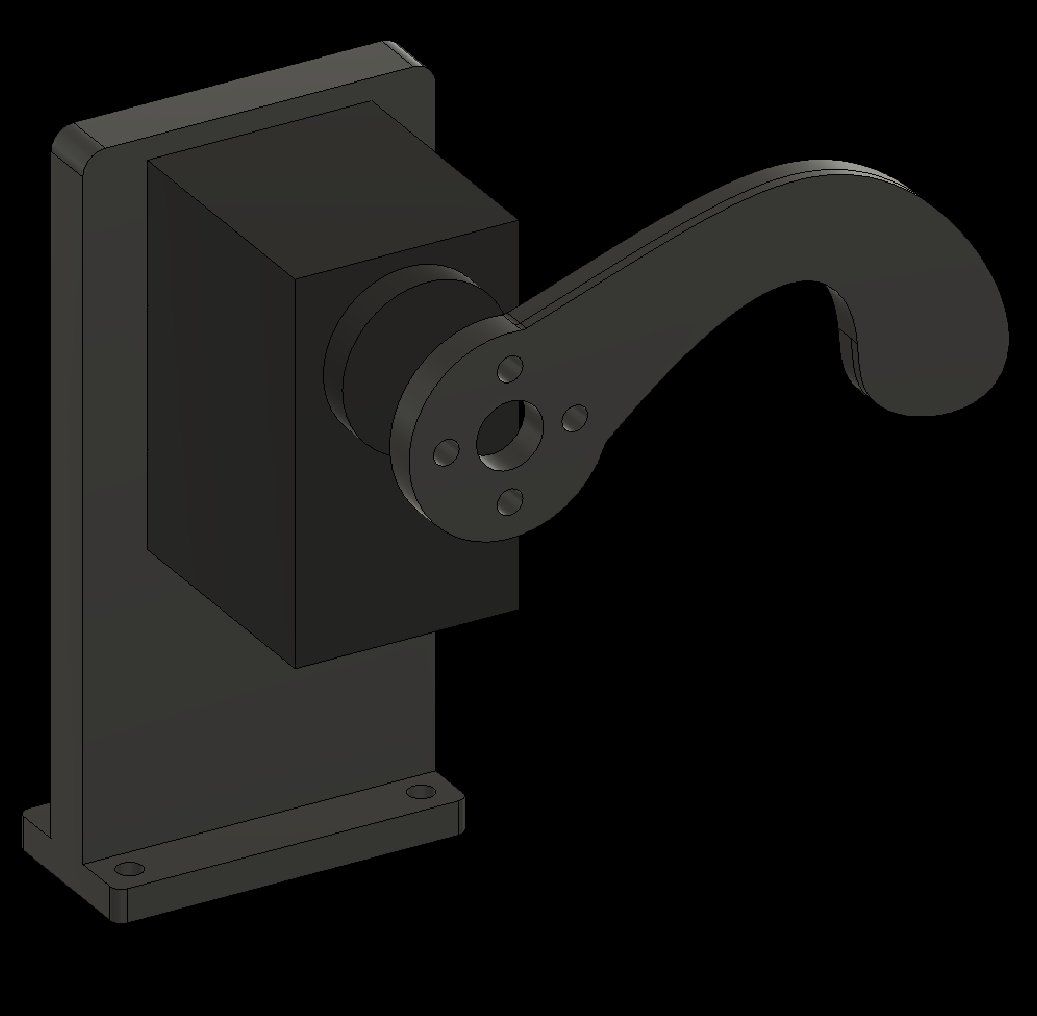
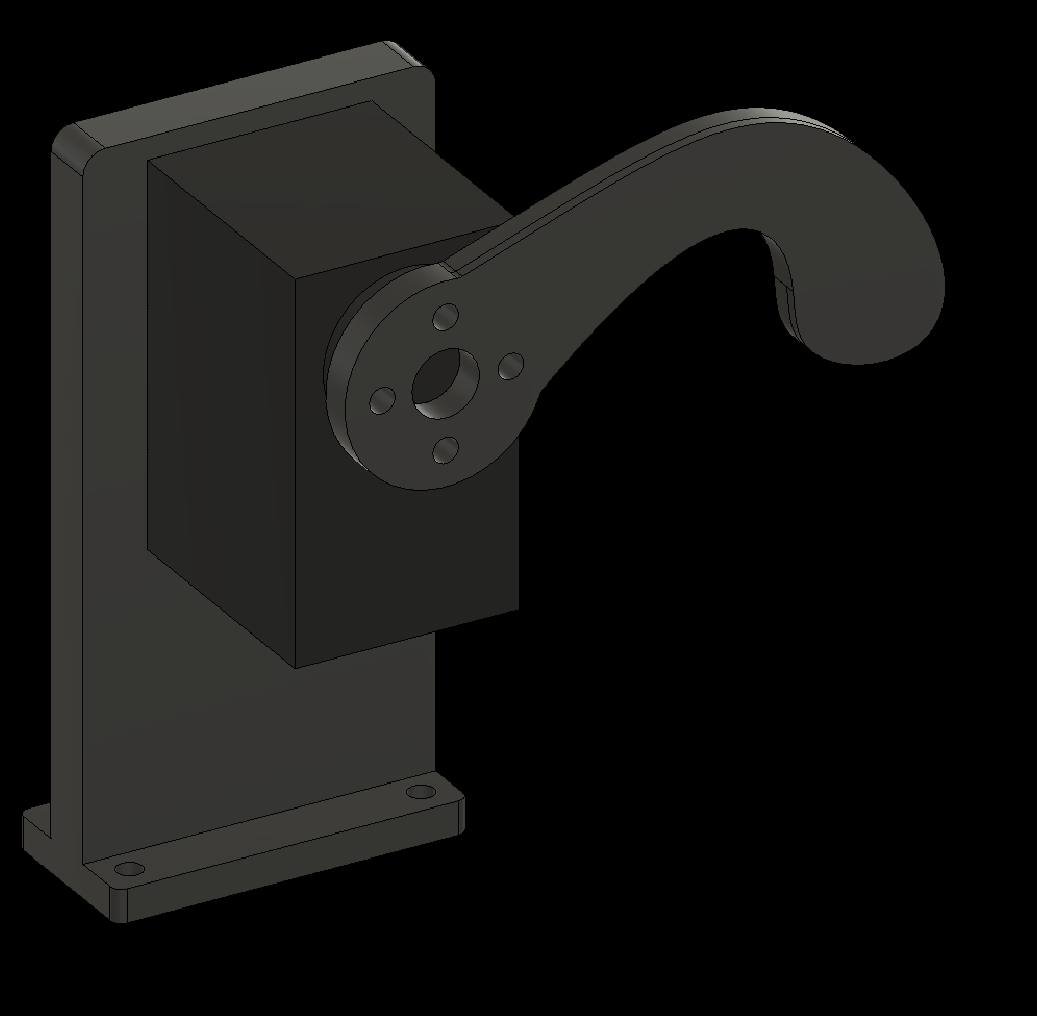
3.5 Complete the Arms (2x)
3. Assembling Individual Components
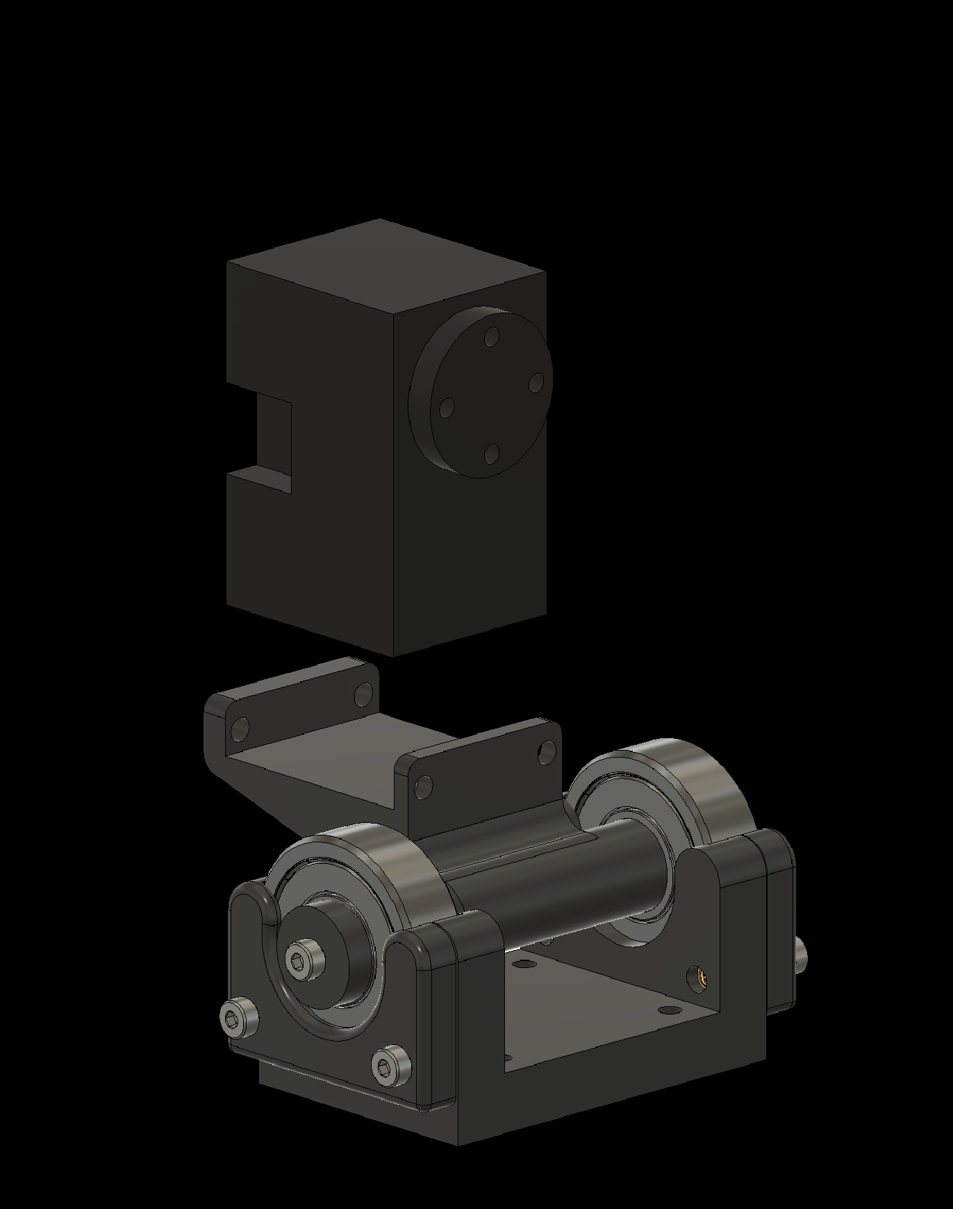
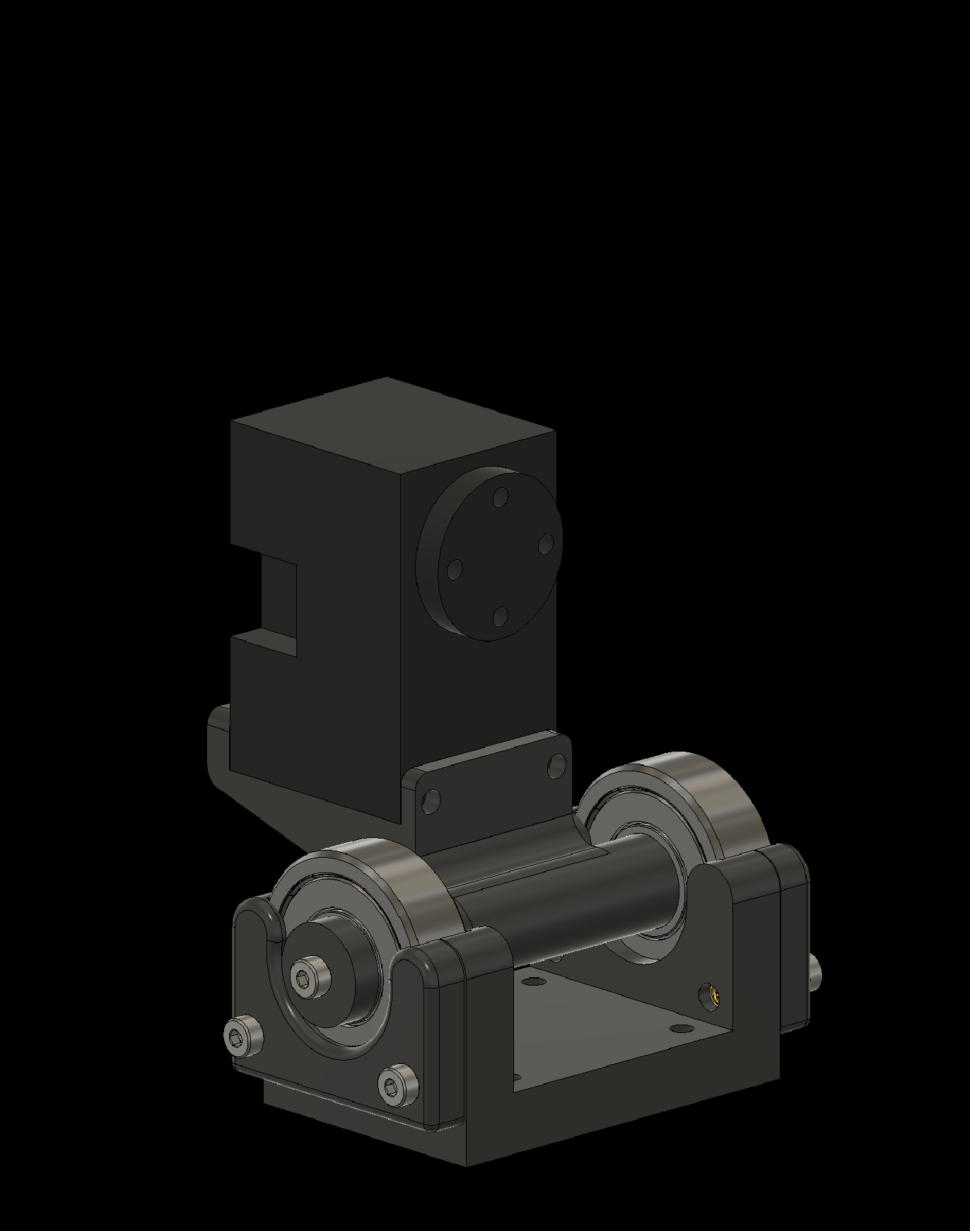
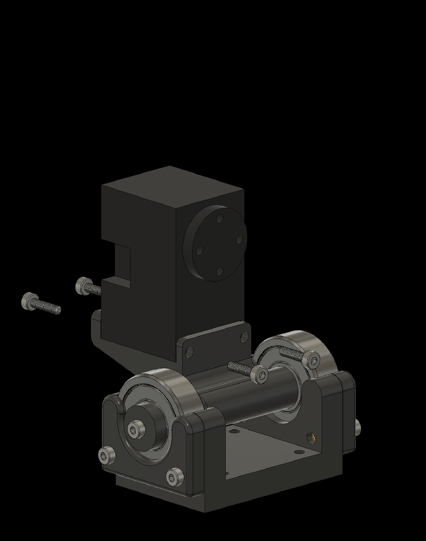
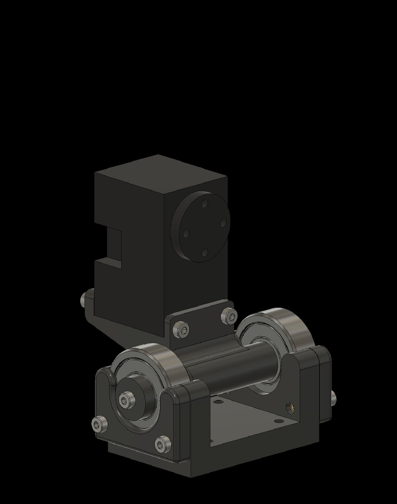
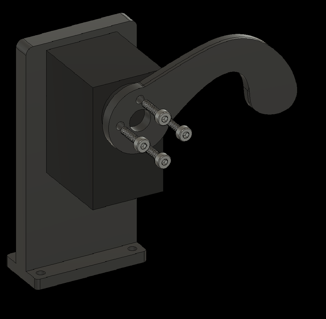
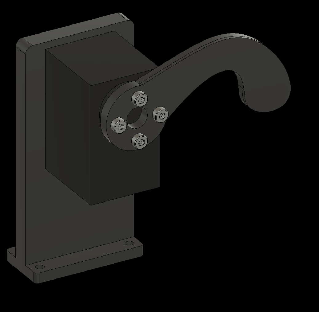
3.6a Attach the Fire Button Servo
3. Assembling Individual Components
3.6b Attach the Fire Finger to the Servo
4. Attaching Components to the Baseplate
Next, attach the assembled components to the baseplate. Apply a thread-locking compound to all screws.
4. Attaching Components to the Baseplate
4.1 Attach Corner 1 to the baseplate

4. Attaching Components to the Baseplate
4.2 Attach Corner 2 to the baseplate

4. Attaching Components to the Baseplate
4.3 Attach Corner 3 to the baseplate


4. Attaching Components to the Baseplate
4.4 Attach Corner 4 to the baseplate


4. Attaching Components to the Baseplate
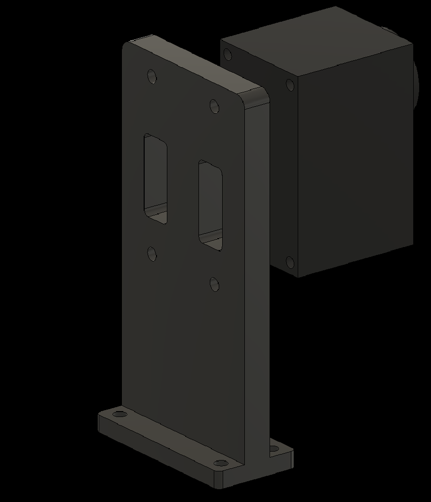
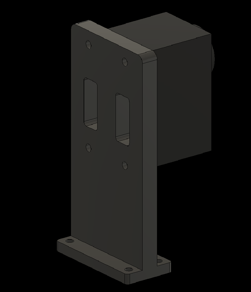
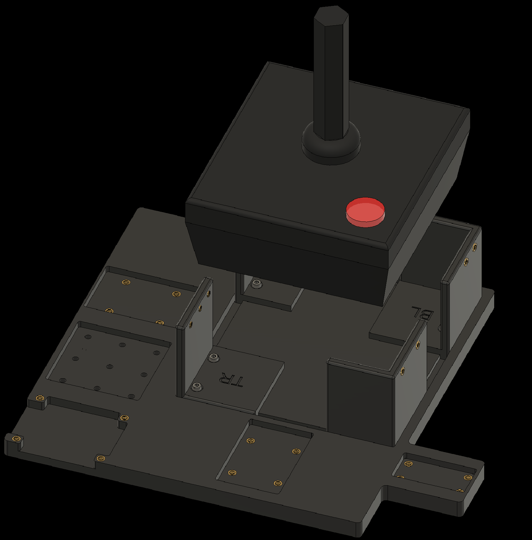
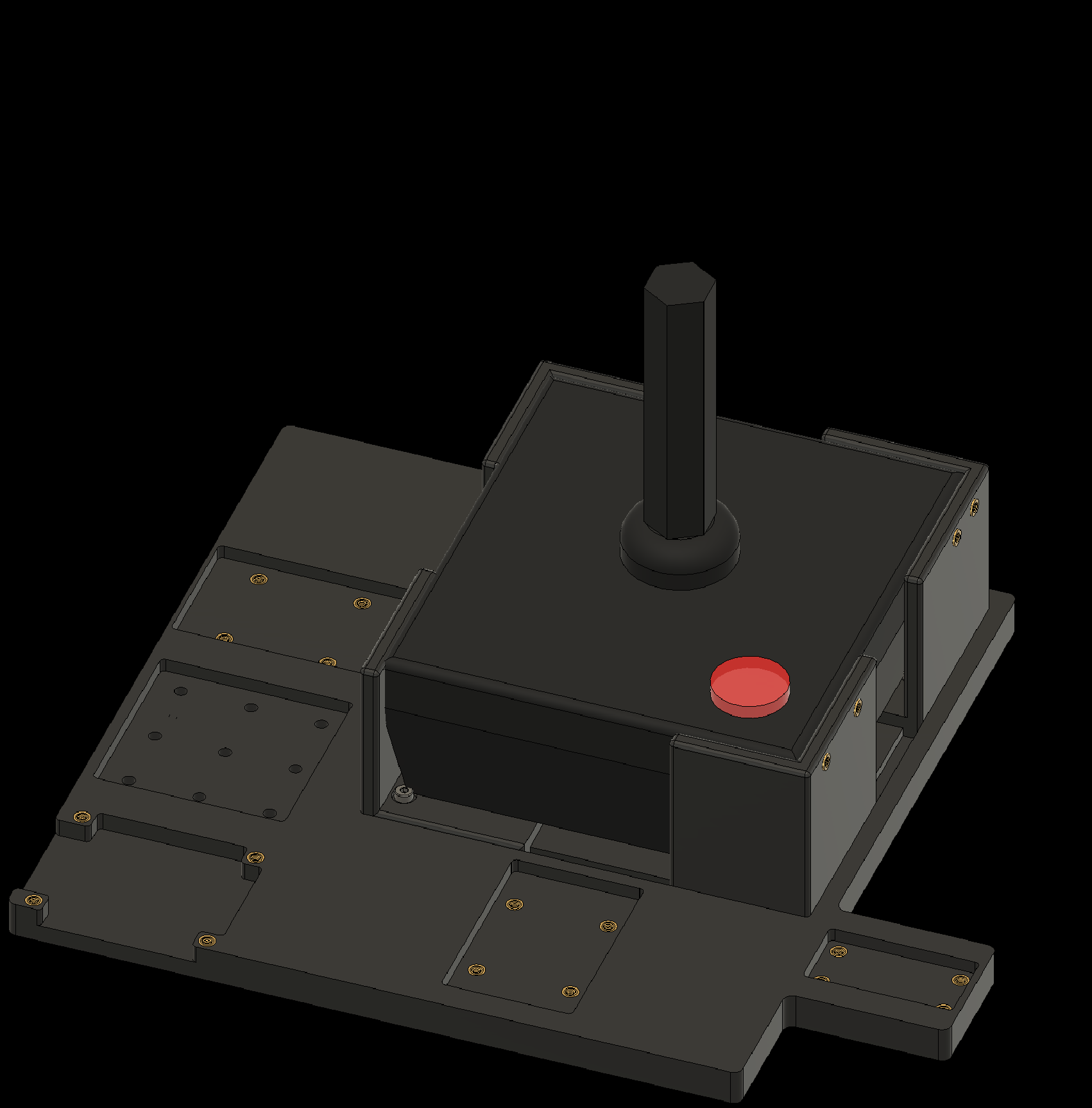
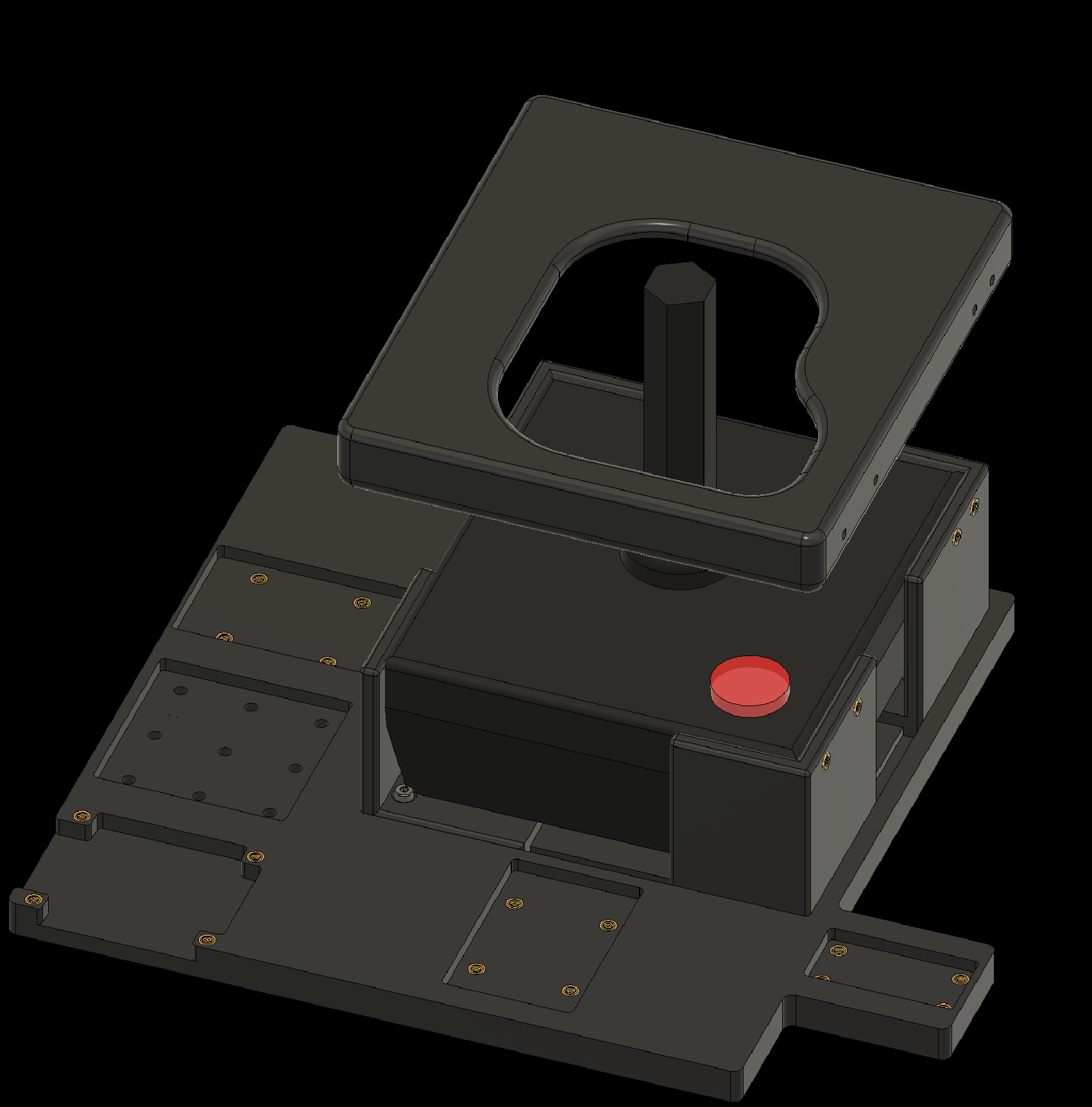
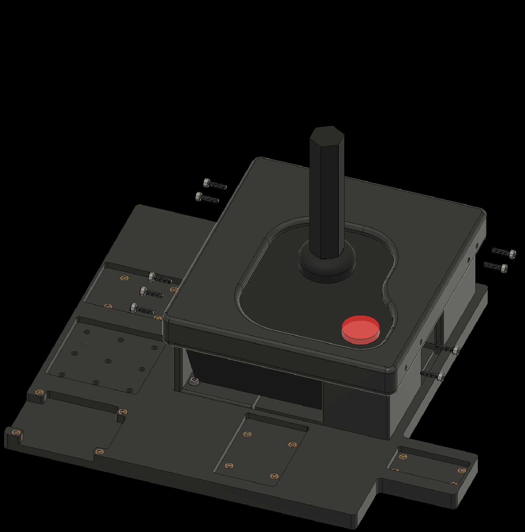
4.5 Attach the CX40+ Controller to the baseplate


4. Attaching Components to the Baseplate
4.6 Attach the Left-Right Arm to the baseplate


4. Attaching Components to the Baseplate
4.7 Attach the Up-Down Arm to the baseplate


4. Attaching Components to the Baseplate
4.8 Attach the Fire Finger to the baseplate

4. Attaching Components to the Baseplate
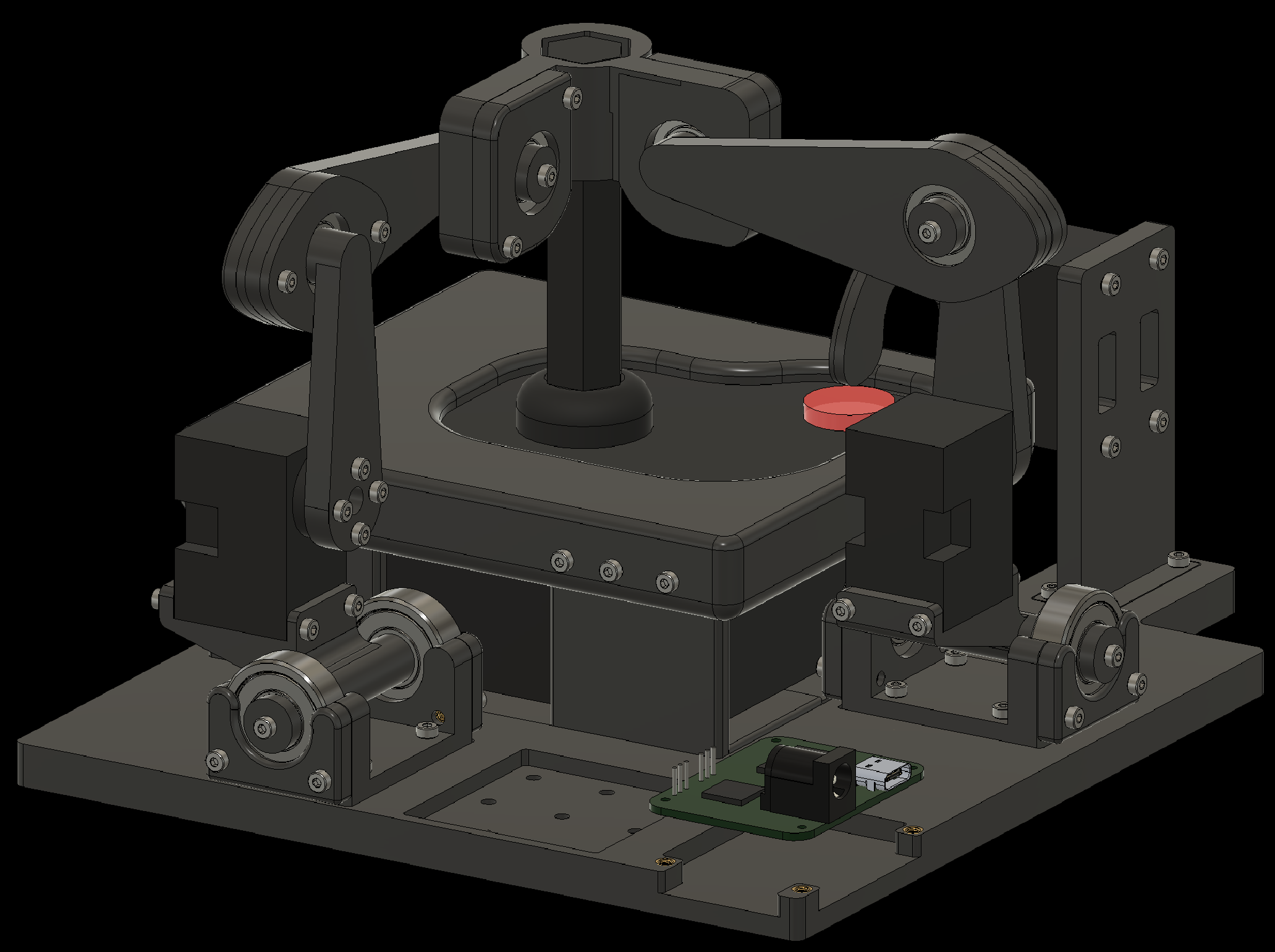
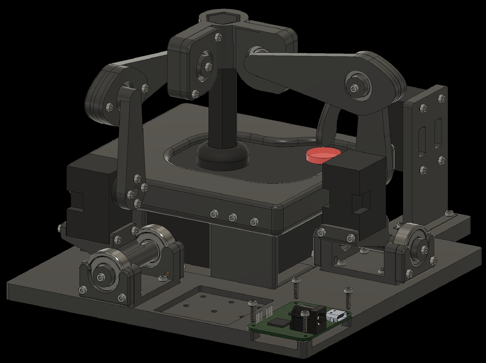
4.9 Attach the Waveshare Serial Bus Servo Drive Board to the baseplate


5. Wiring the Components
Finally, connect the Dynamixel servos to each other and to the Waveshare Serial Bus Servo Drive Board as shown on the next slides. The wires that ship with the Dynamixels do not fit the connector on the Waveshare board. Trim the outer edge of the connector on the board with a flat screwdriver so it fits.
5. Wiring the Components
5. Wiring the Components
When connecting the wire to the servo board, as shown in the next slides, pay close attention to the orientation of the connector. We show the three wires in different colors to make the correct orientation clear.
5. Wiring the Components
6. Testing the Robotroller
To use the Robotroller to recreate the Upperbound 2025 demo, see this guide.
To use the Robotroller as used in the RLC 2026 paper, see this guide.