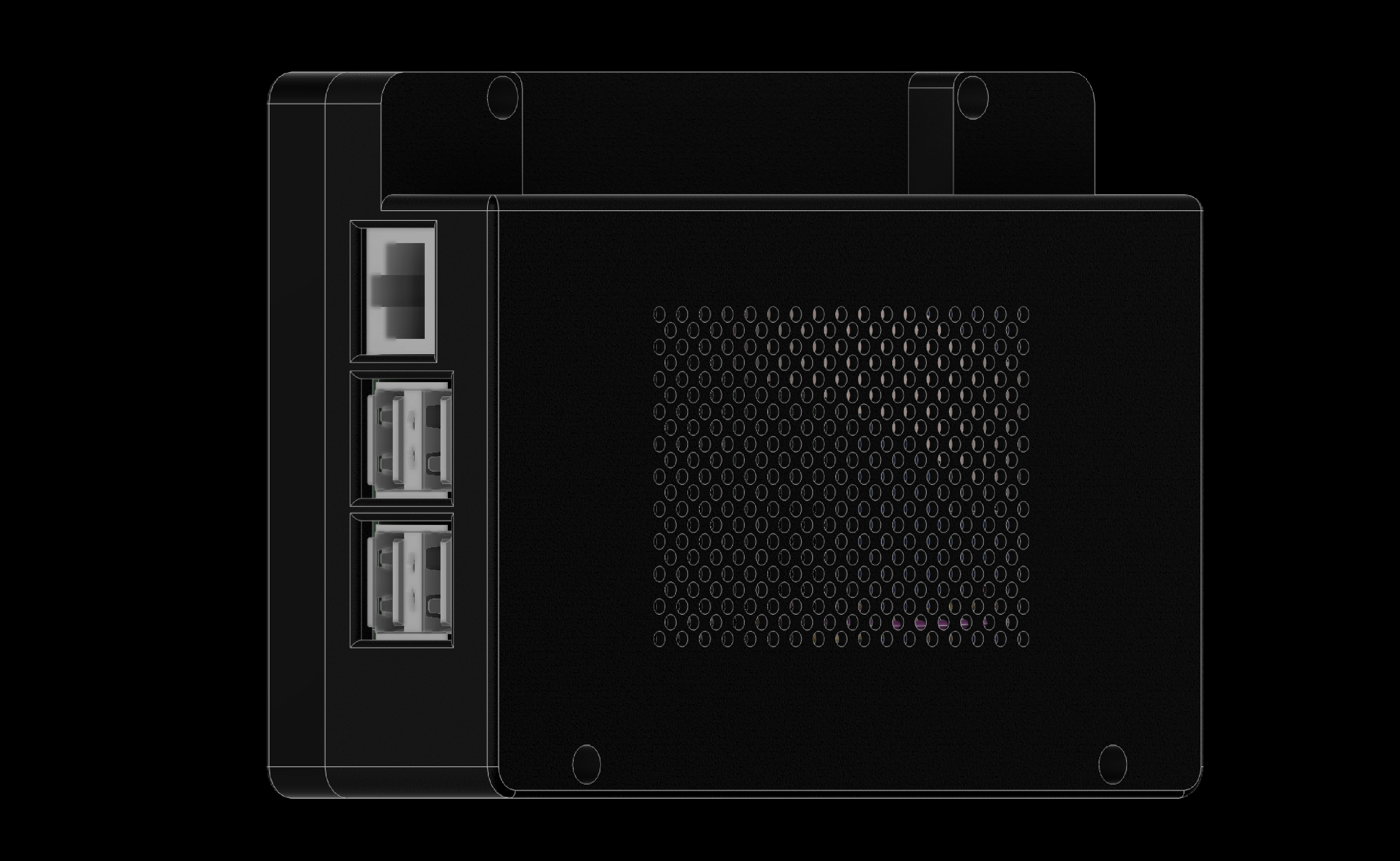
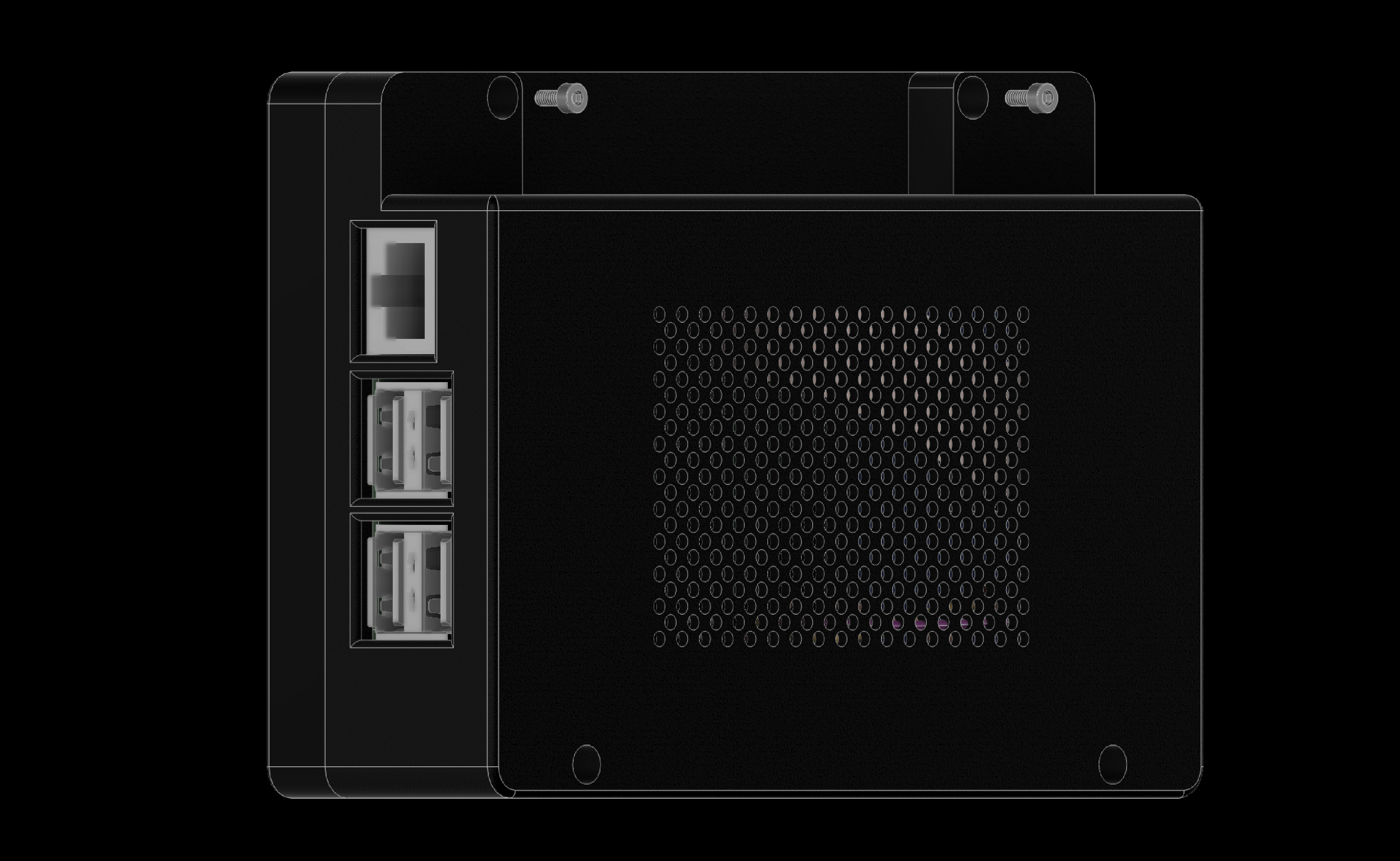
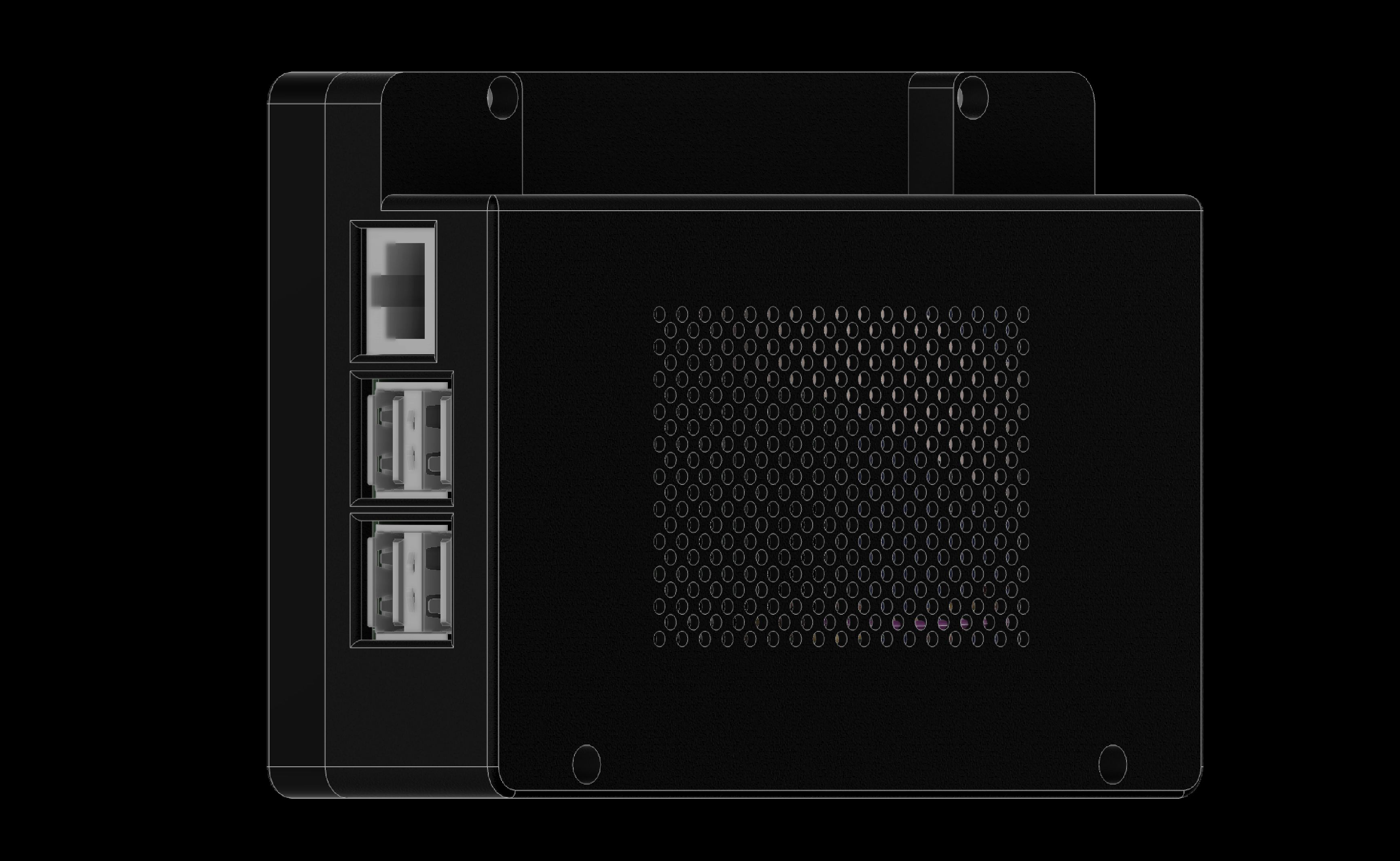
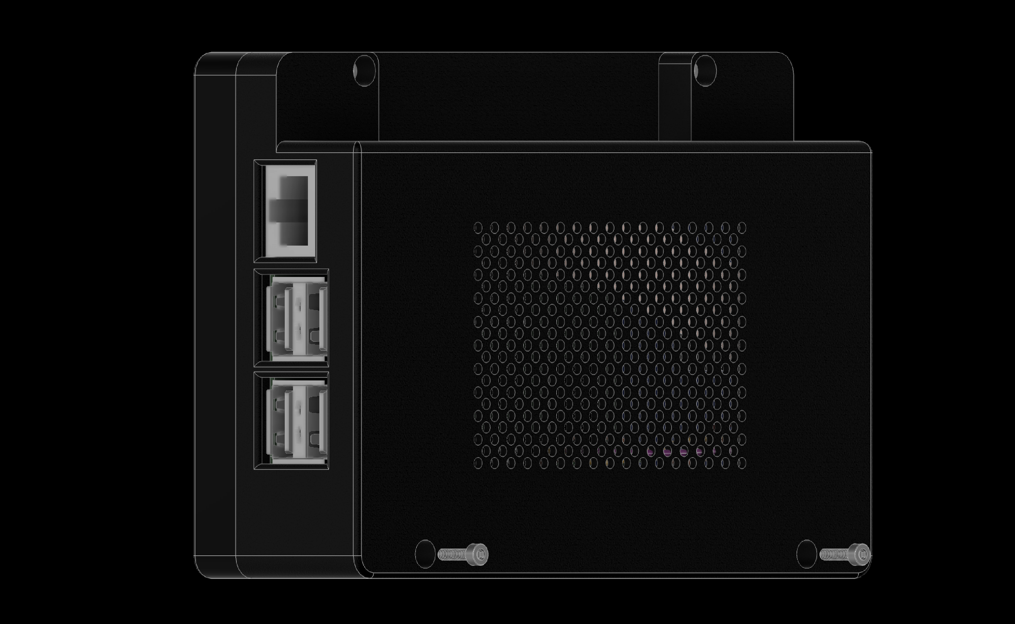
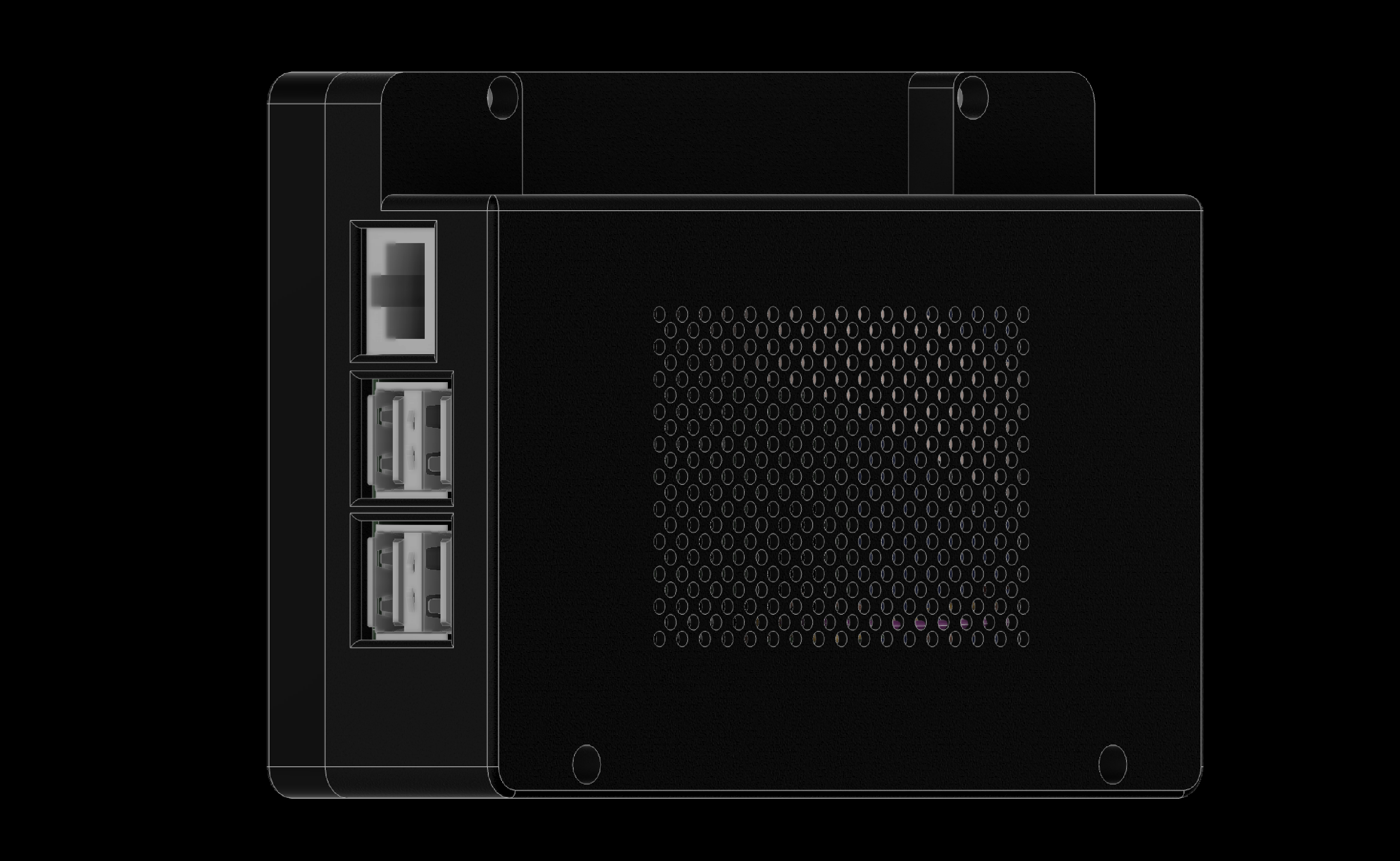
The Atari Devbox is a compact device that uses a Raspberry Pi 5 as its compute unit and a 5-inch Waveshare display. We designed a custom chassis in Autodesk Fusion that can be 3D-printed to house the components. Since the Raspberry Pi 5 lacks a built-in DB9 port required by the Atari CX40+ joystick, we connected a male DB9 connector directly to the GPIO pins of the Raspberry Pi 5. This connector is exposed through the chassis of the Atari Devbox.
It requires two types of components—ones that can be 3D printed and ones that need to be bought. The printed parts can be produced on a home 3D printer or a commercial service. Where helpful, we link to suppliers for purchased items. The parts to print and parts to buy are listed below, with the assembly guide at the end.
Assembly guide
Atari Devbox Assembly Guide
Use arrow keys, or tap or click either side of the slide
Overview
- 3D print the components
- Add threaded inserts
- Connect Raspberry Pi to the 5inch Capacitive Touch Display for Raspberry Pi, DSI Interface, 800×480 (SKU 18396)
- Wire the DB9 connector to GPIO pins
- Assemble the Atari Devbox
1. 3D Print the Components
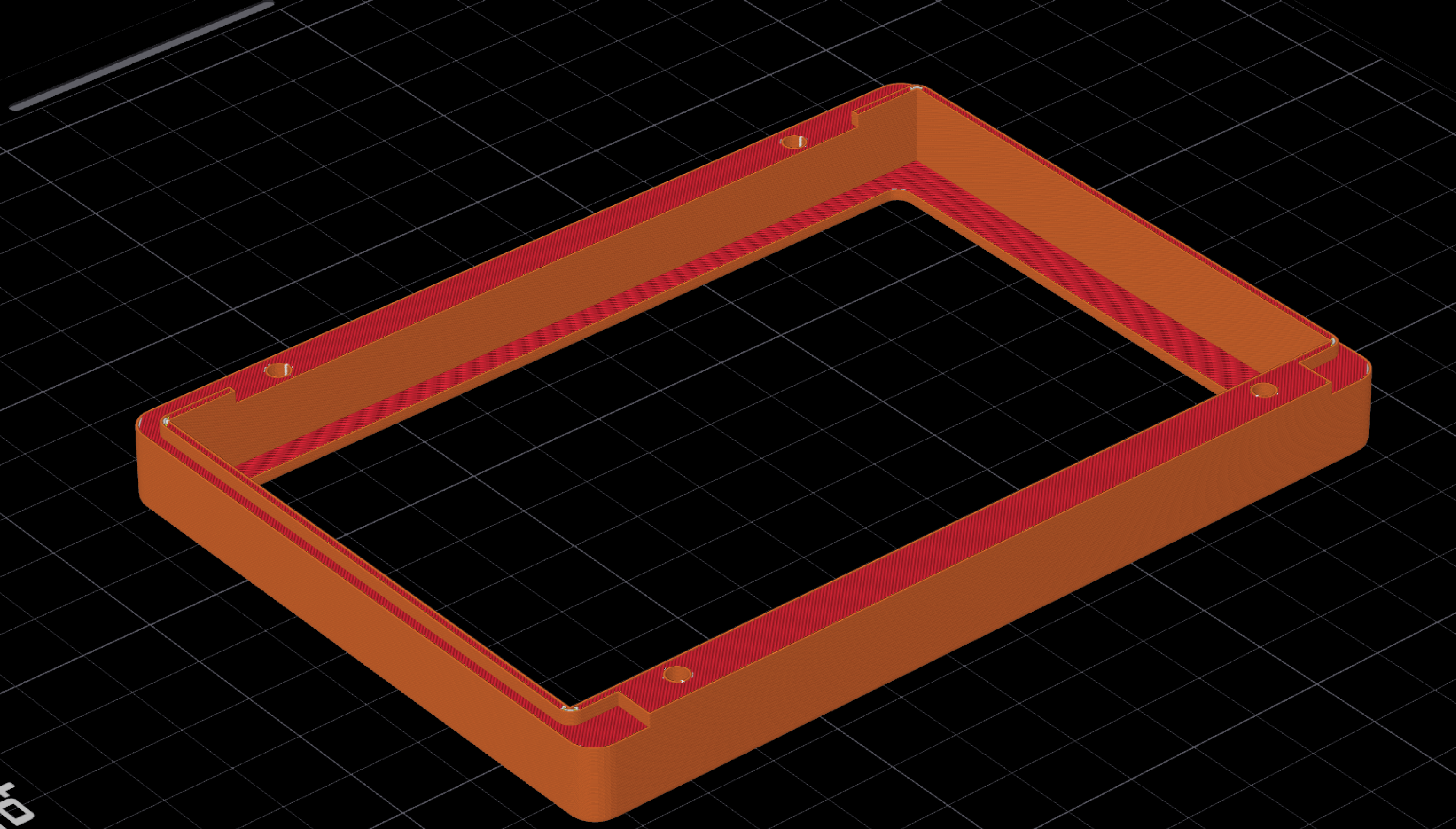
1.1 3D print the front chassis
1. 3D Print the Components
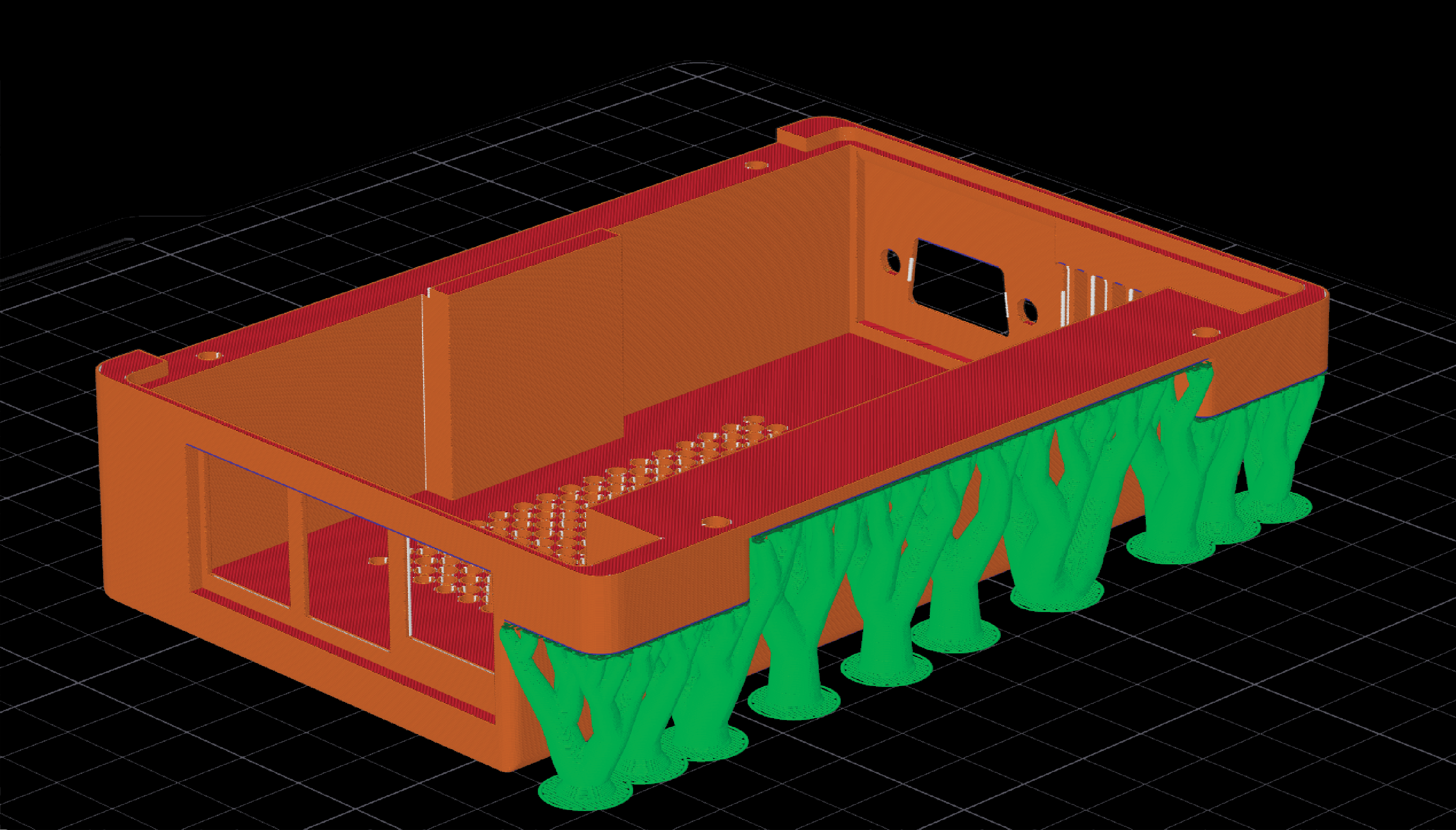
1.2 3D print the back chassis with supports
2. Add Threaded Inserts
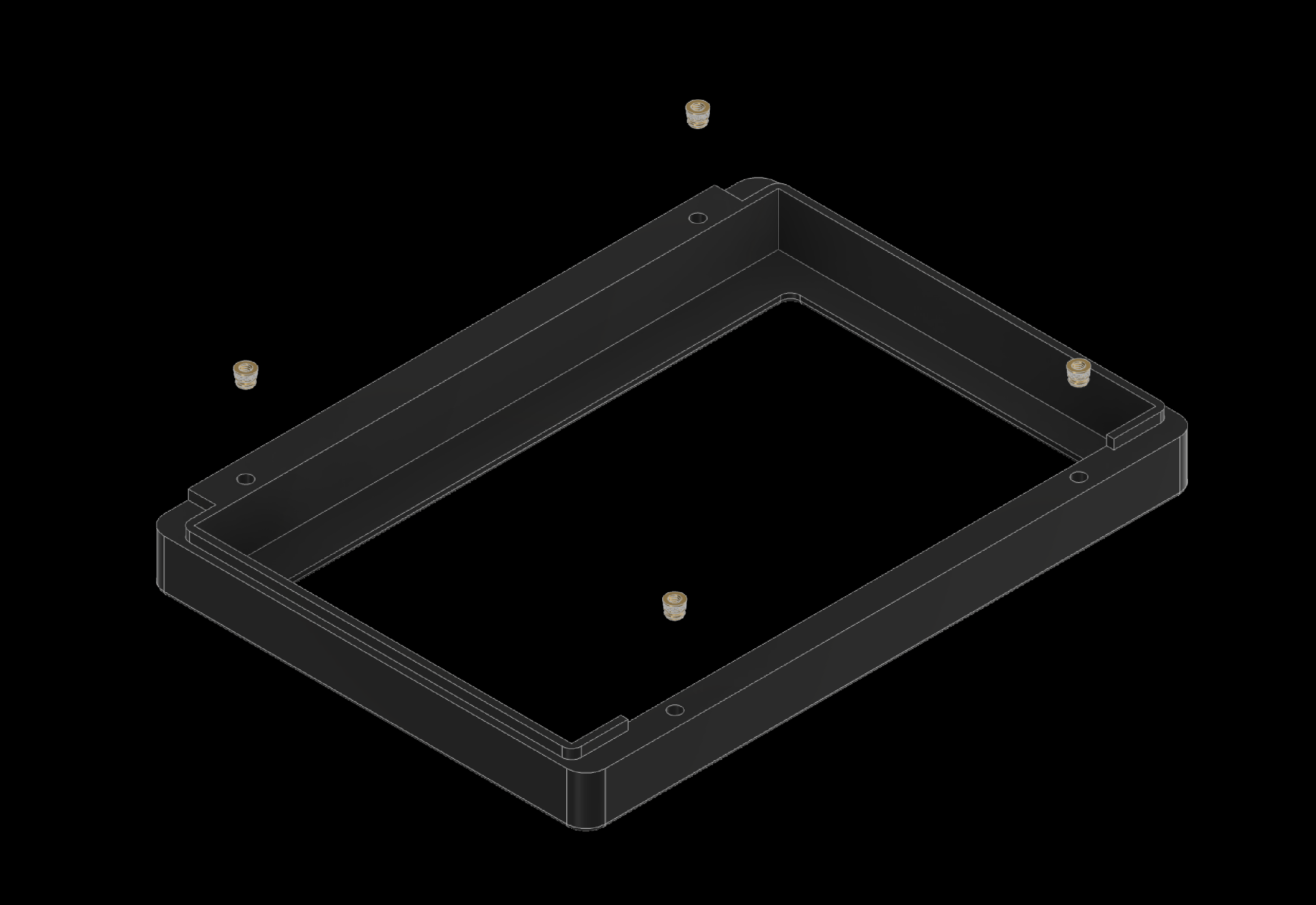
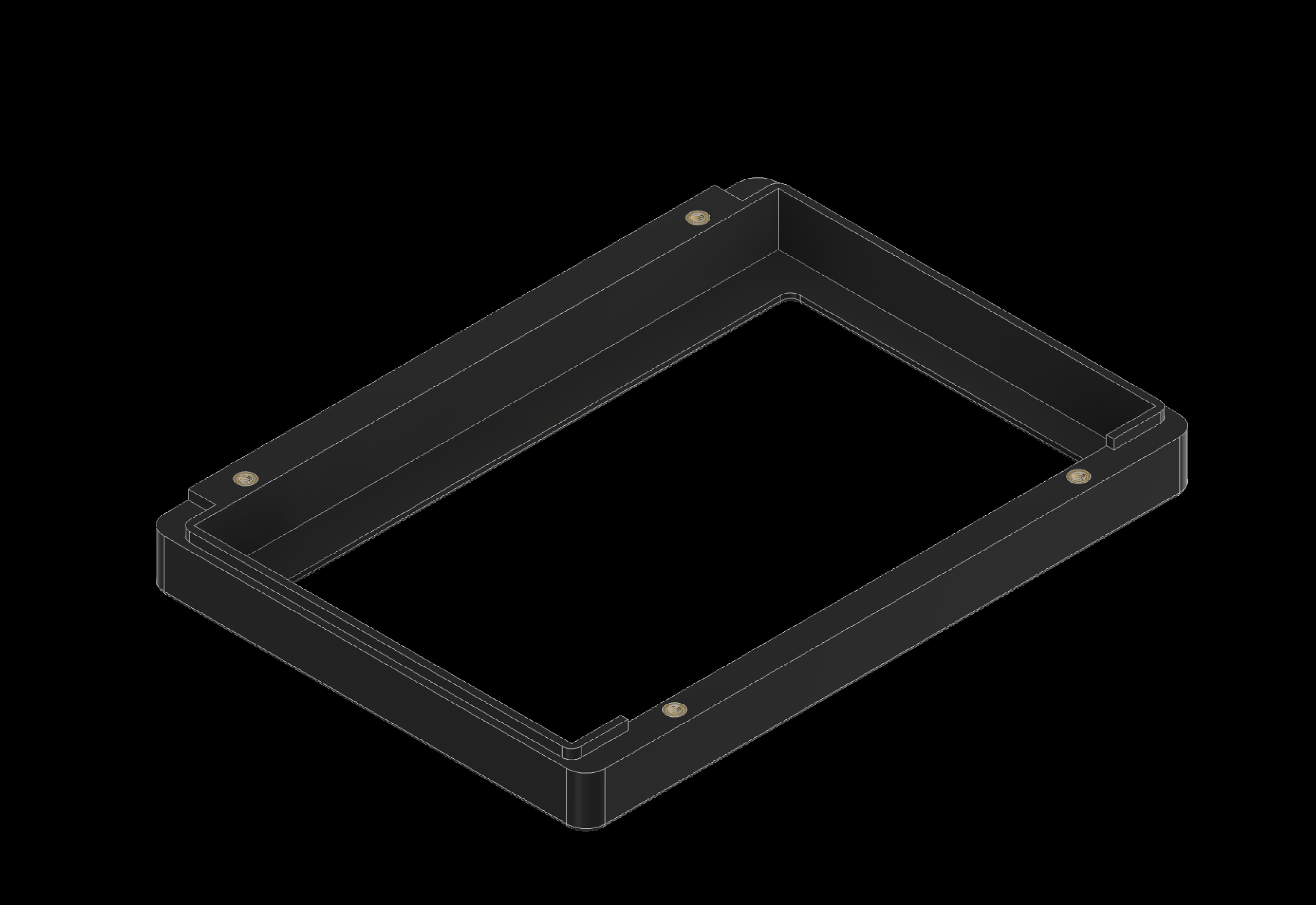
Heat-set the threaded inserts using a soldering iron. The following slides show where to place them.
2. Add Threaded Inserts
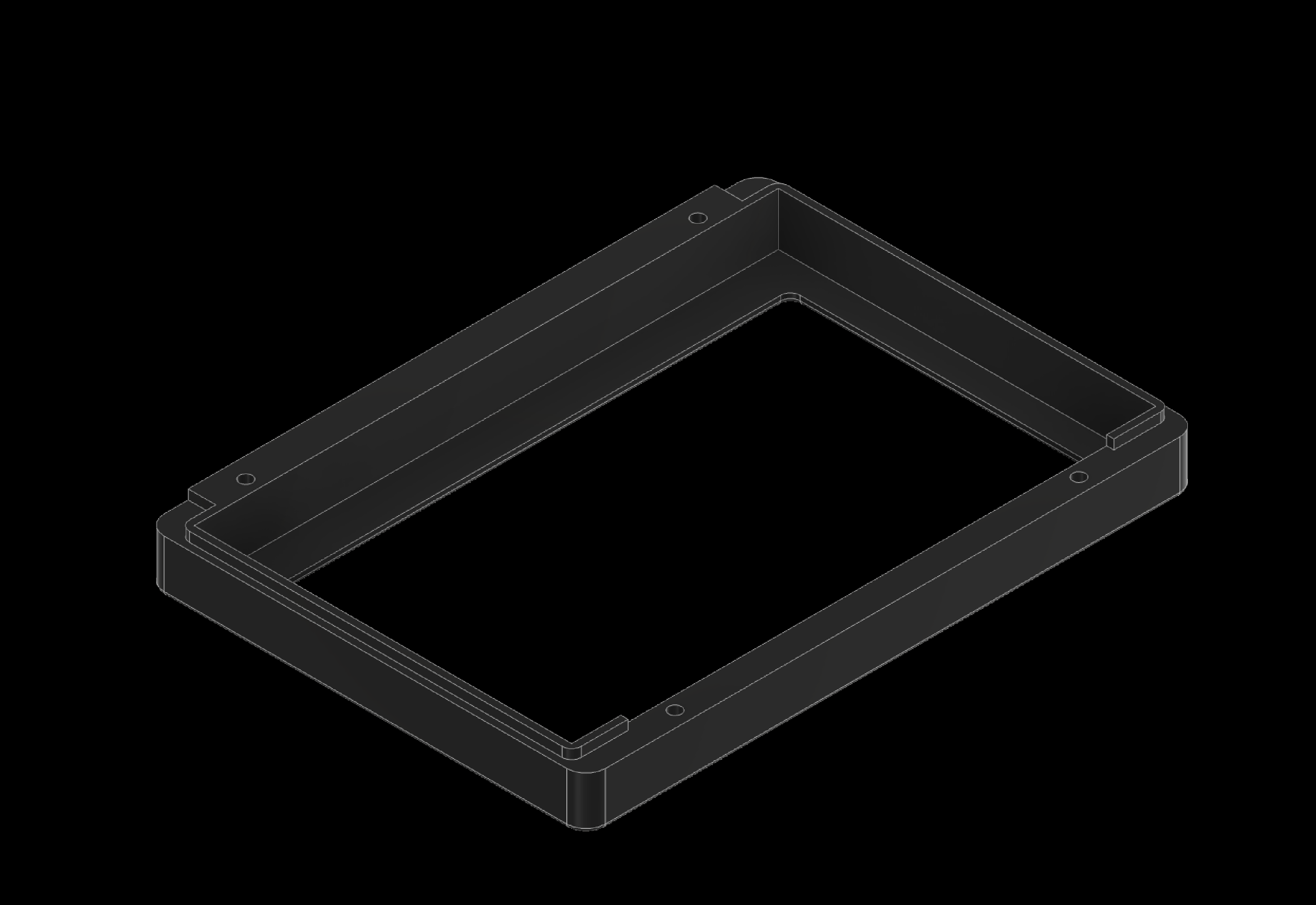
2.1 Front heat sink
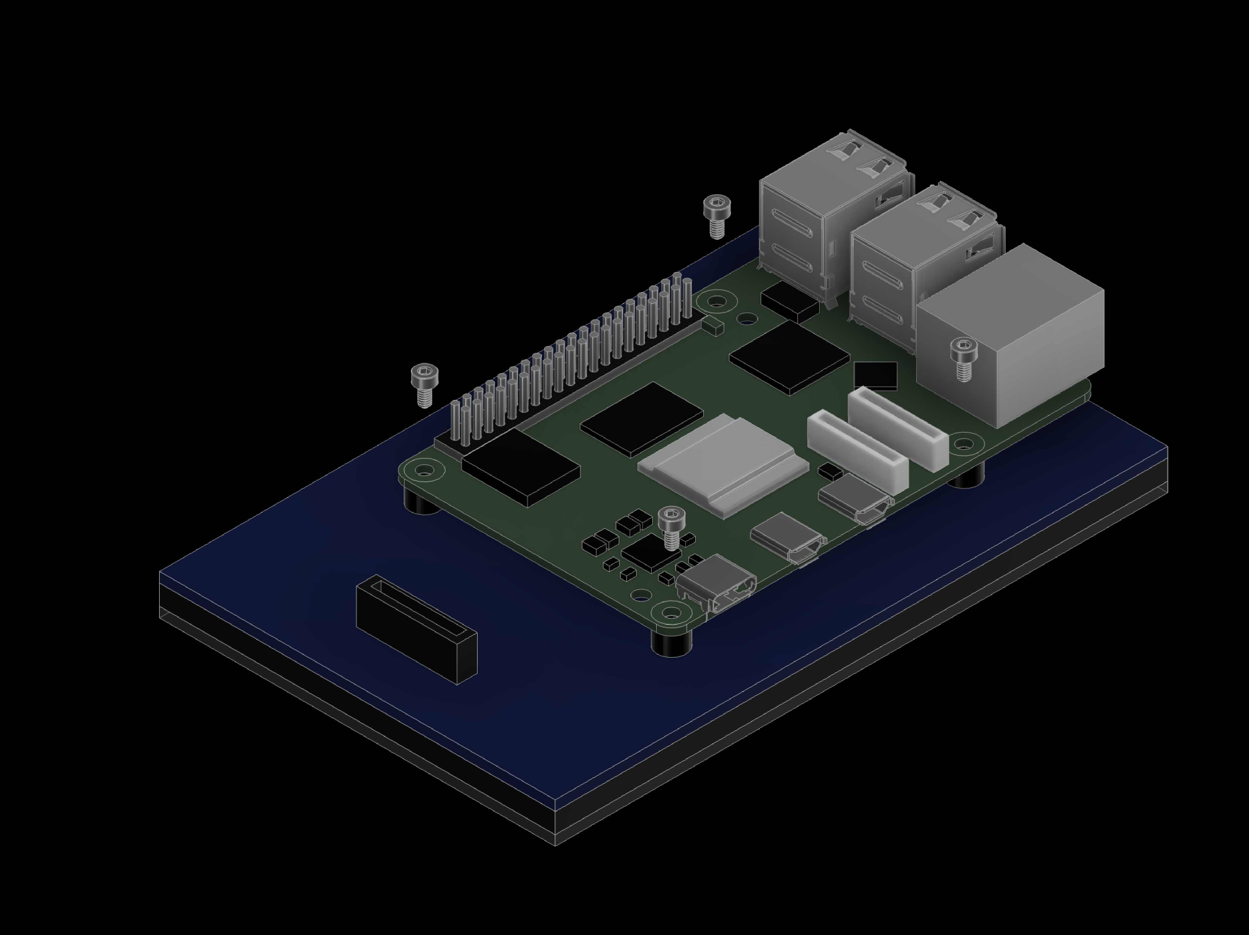
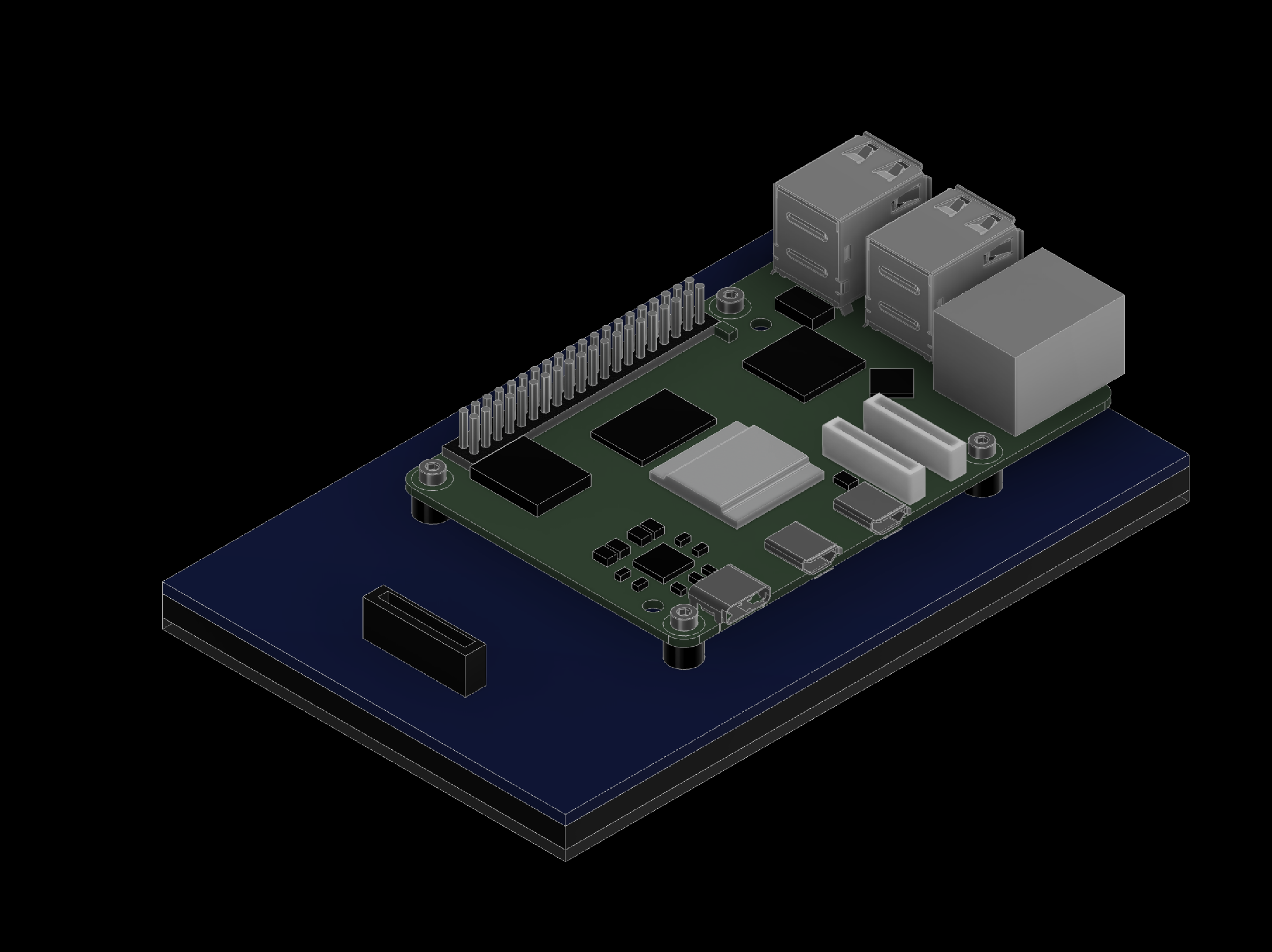
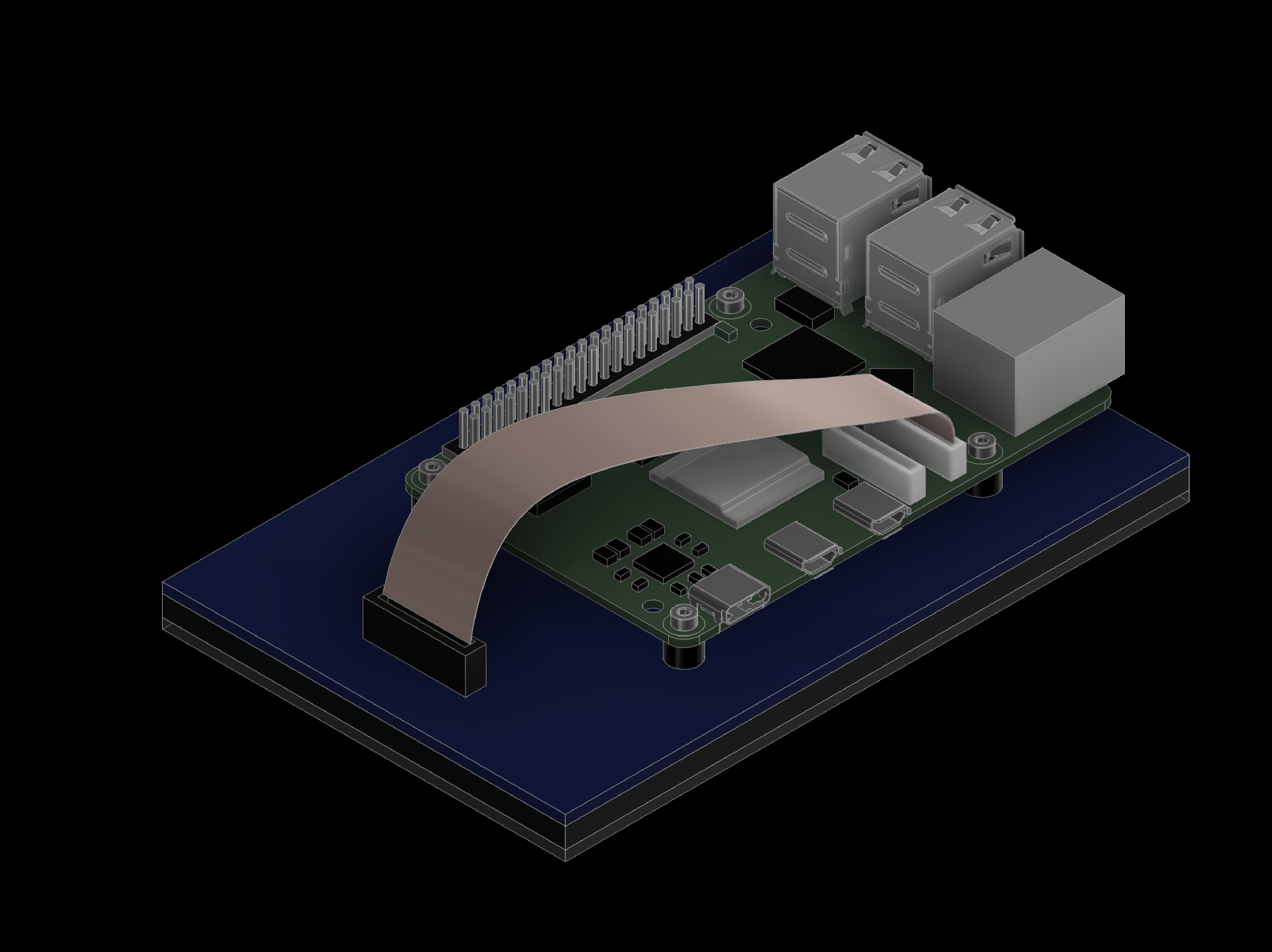
3. Connect Raspberry Pi to 5inch Capacitive Touch Display for Raspberry Pi, DSI Interface, 800×480 (SKU 18396)
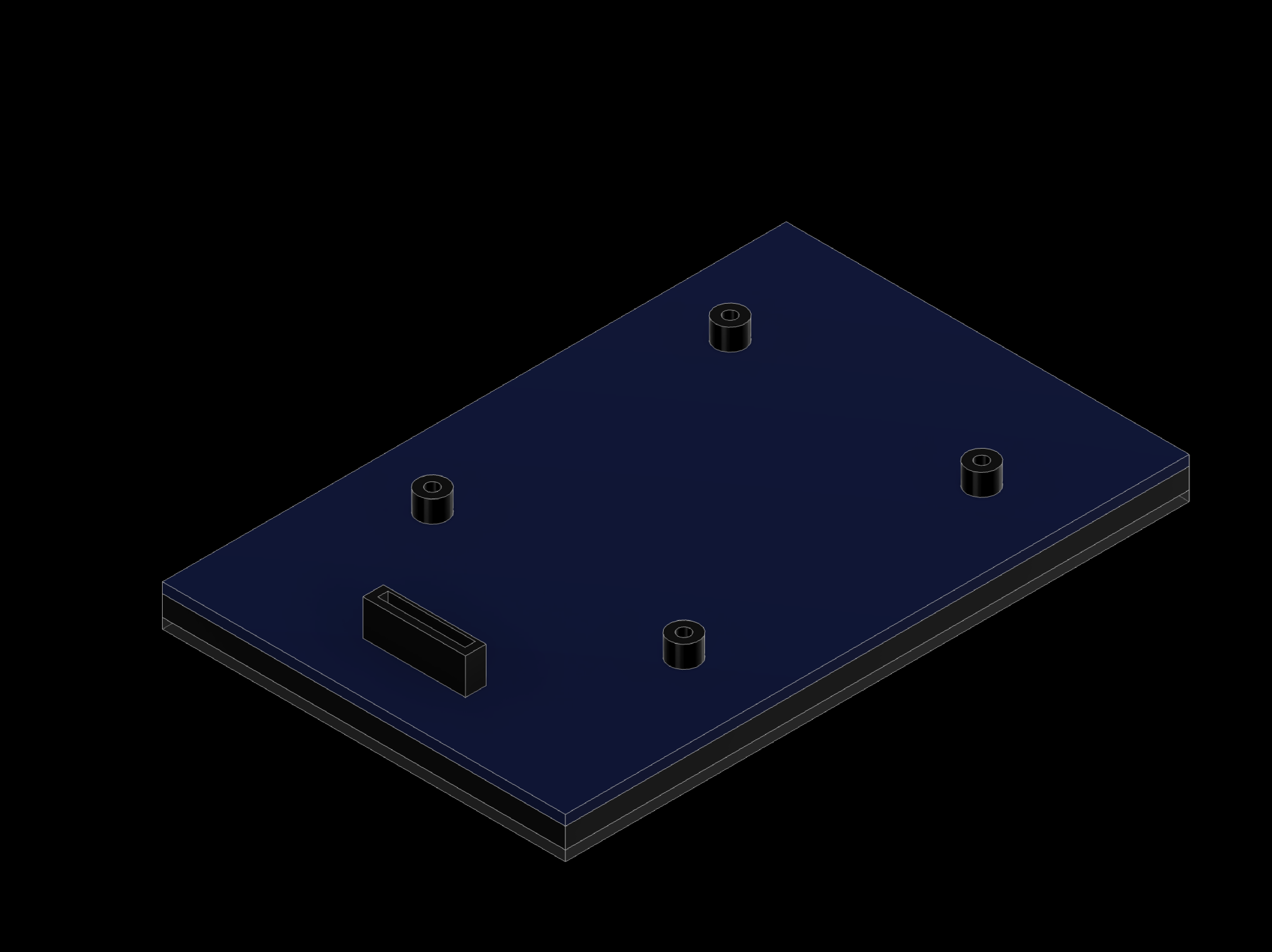
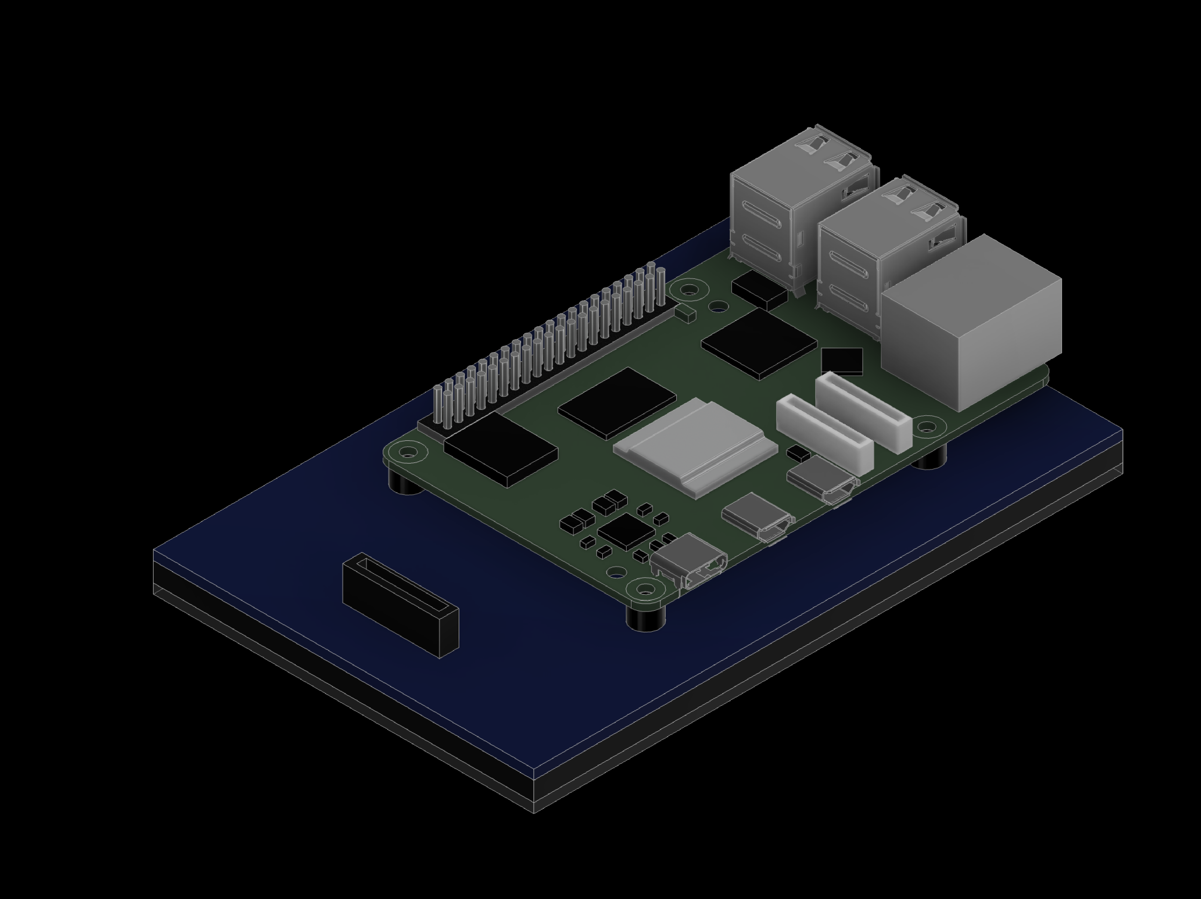
Connect the Raspberry Pi to the 5inch Capacitive Touch Display for Raspberry Pi, DSI Interface, 800×480 (SKU 18396) as shown on the next slides.
3. Connect Raspberry Pi to 5inch Capacitive Touch Display for Raspberry Pi, DSI Interface, 800×480 (SKU 18396)
3.1 Screen & Raspberry Pi
4. Wire the DB9 Connector
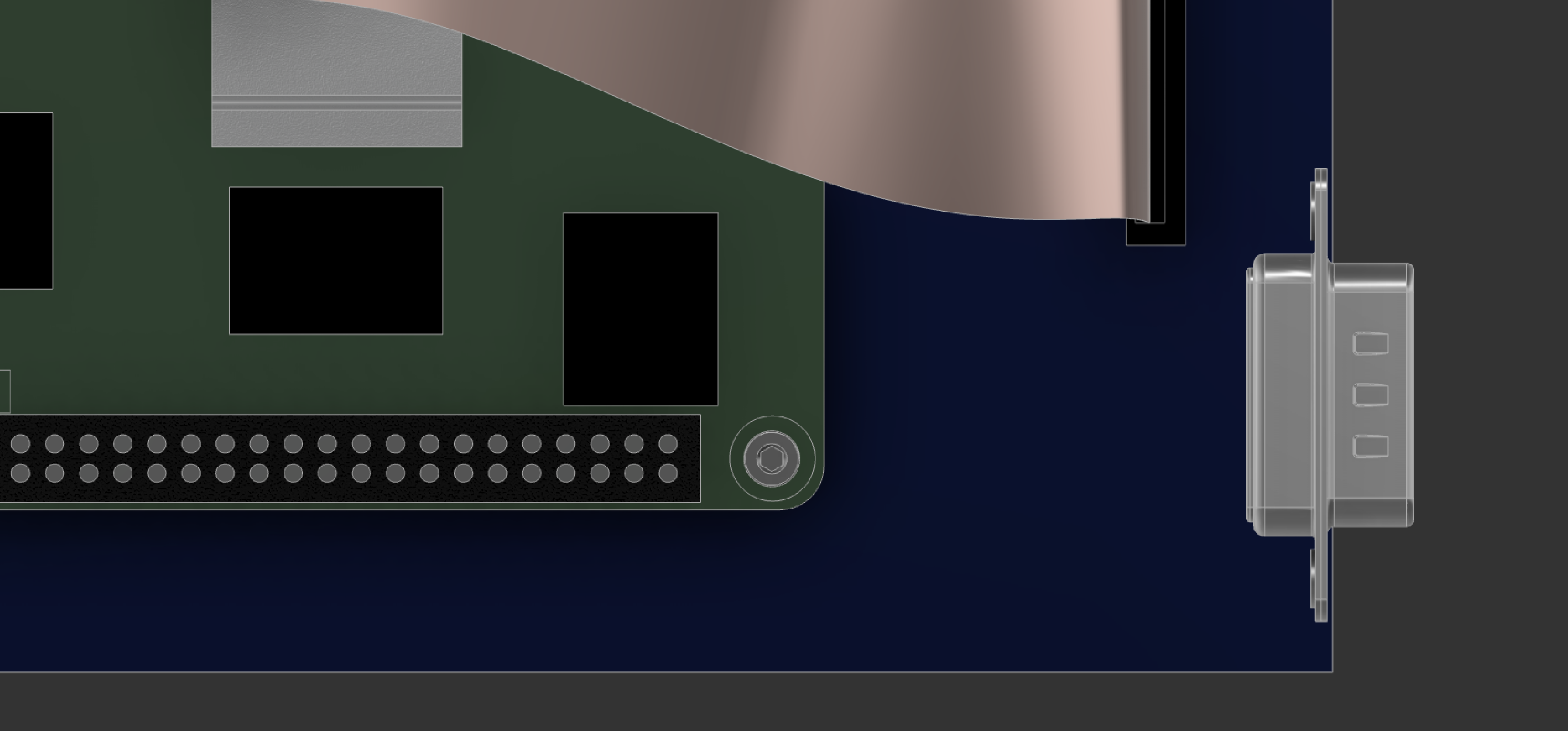
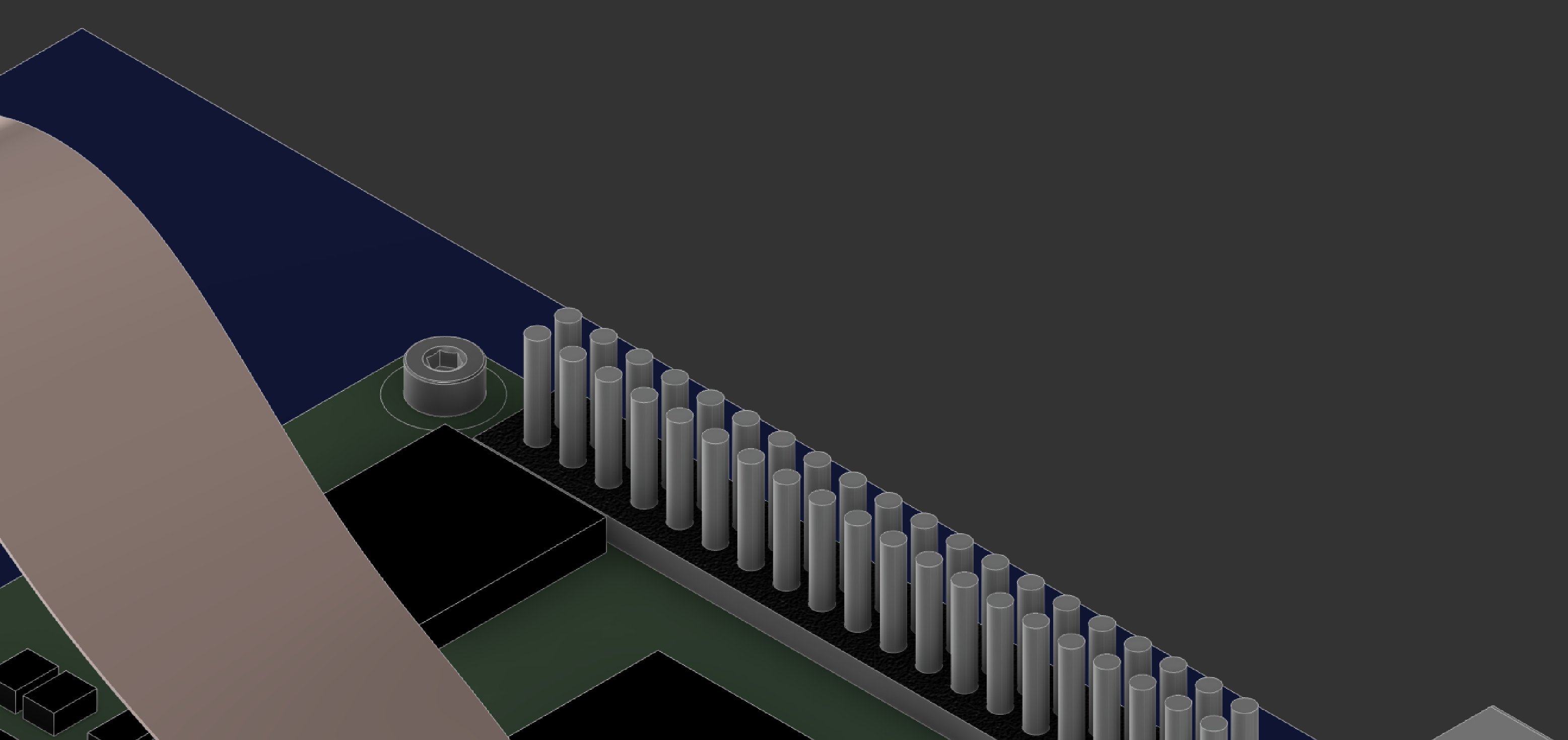
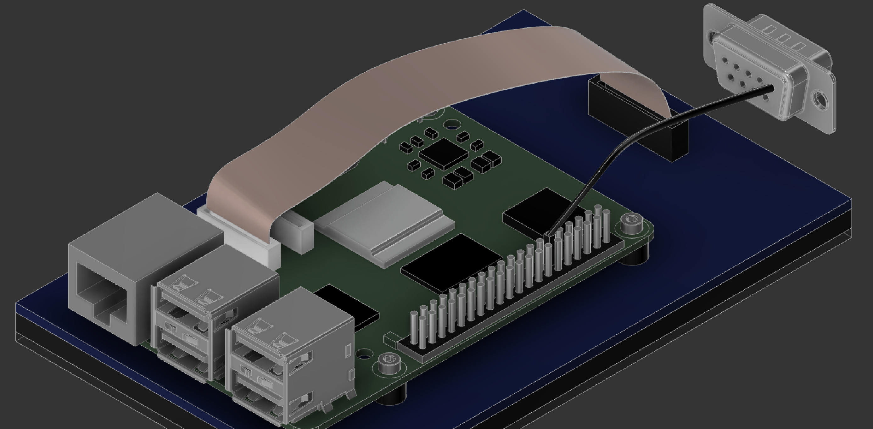
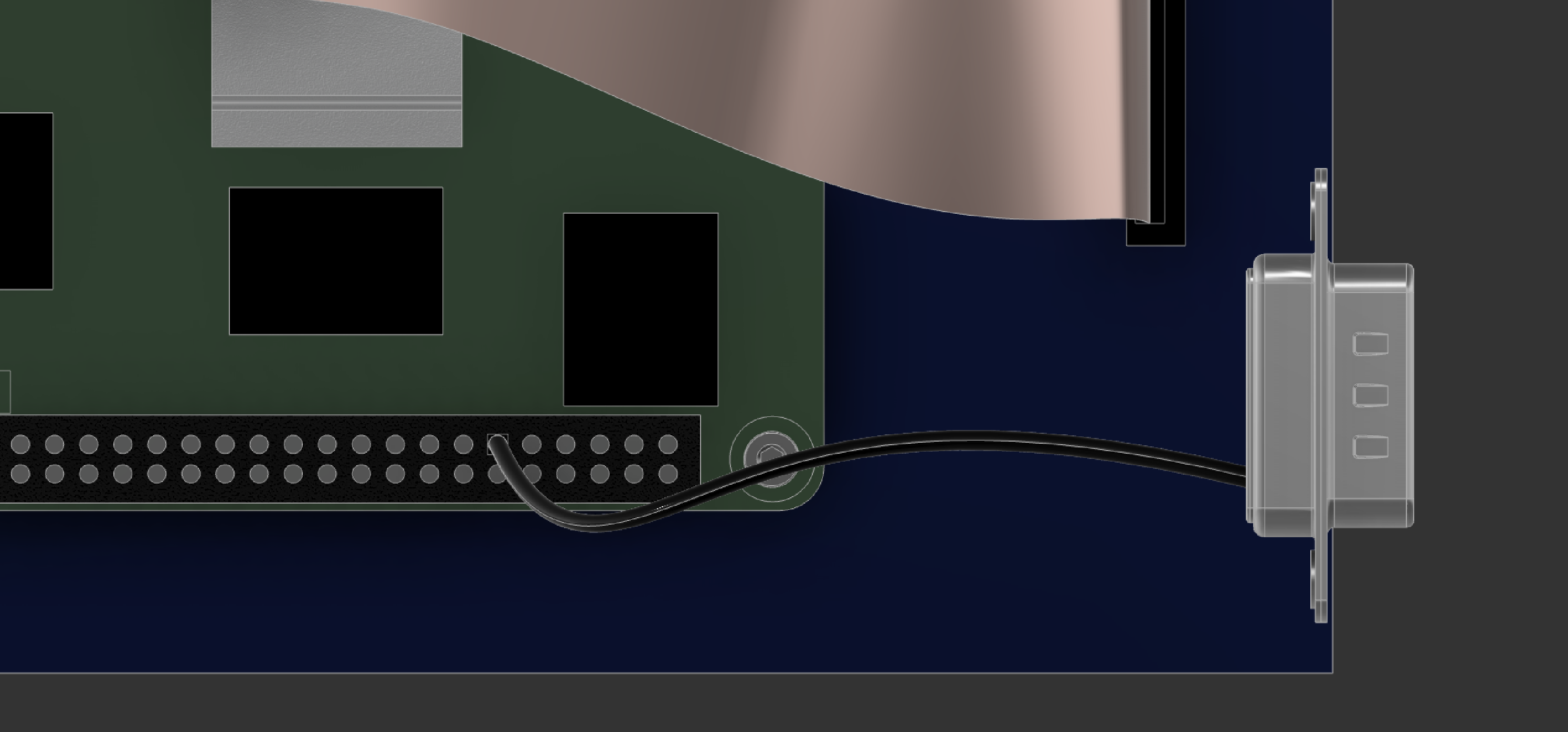
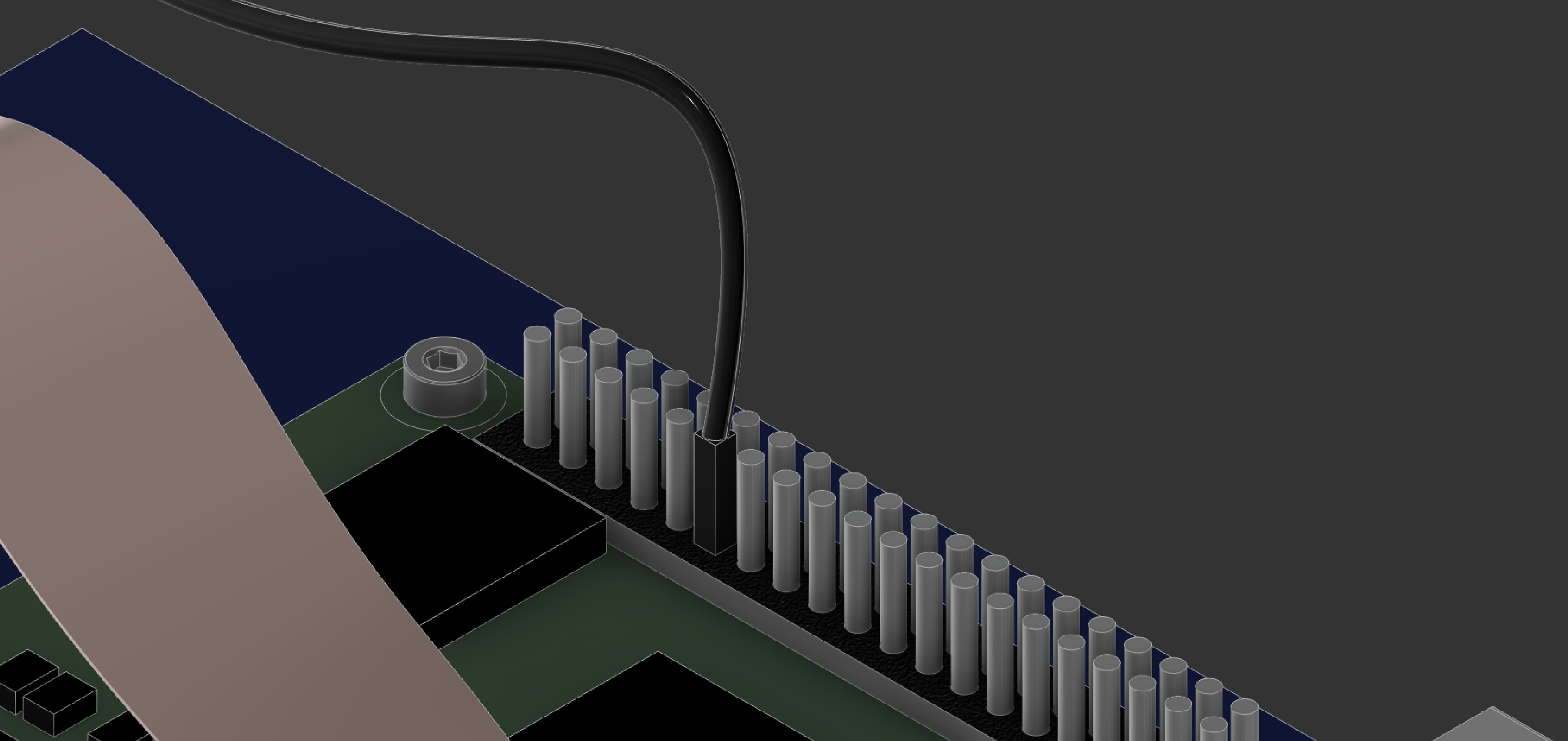
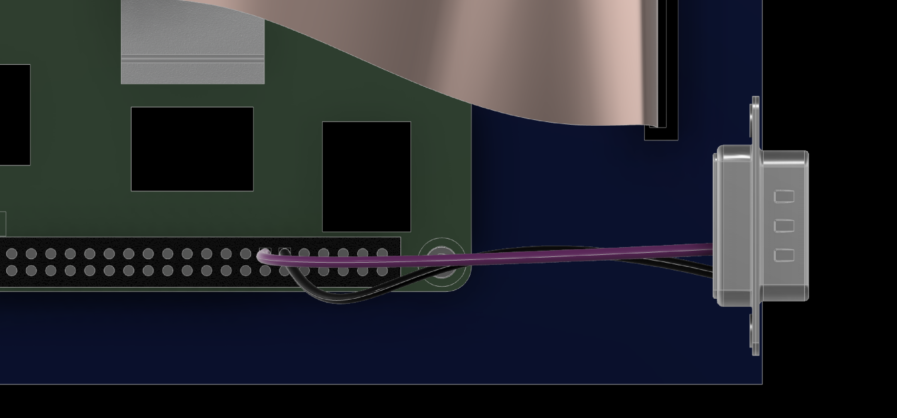
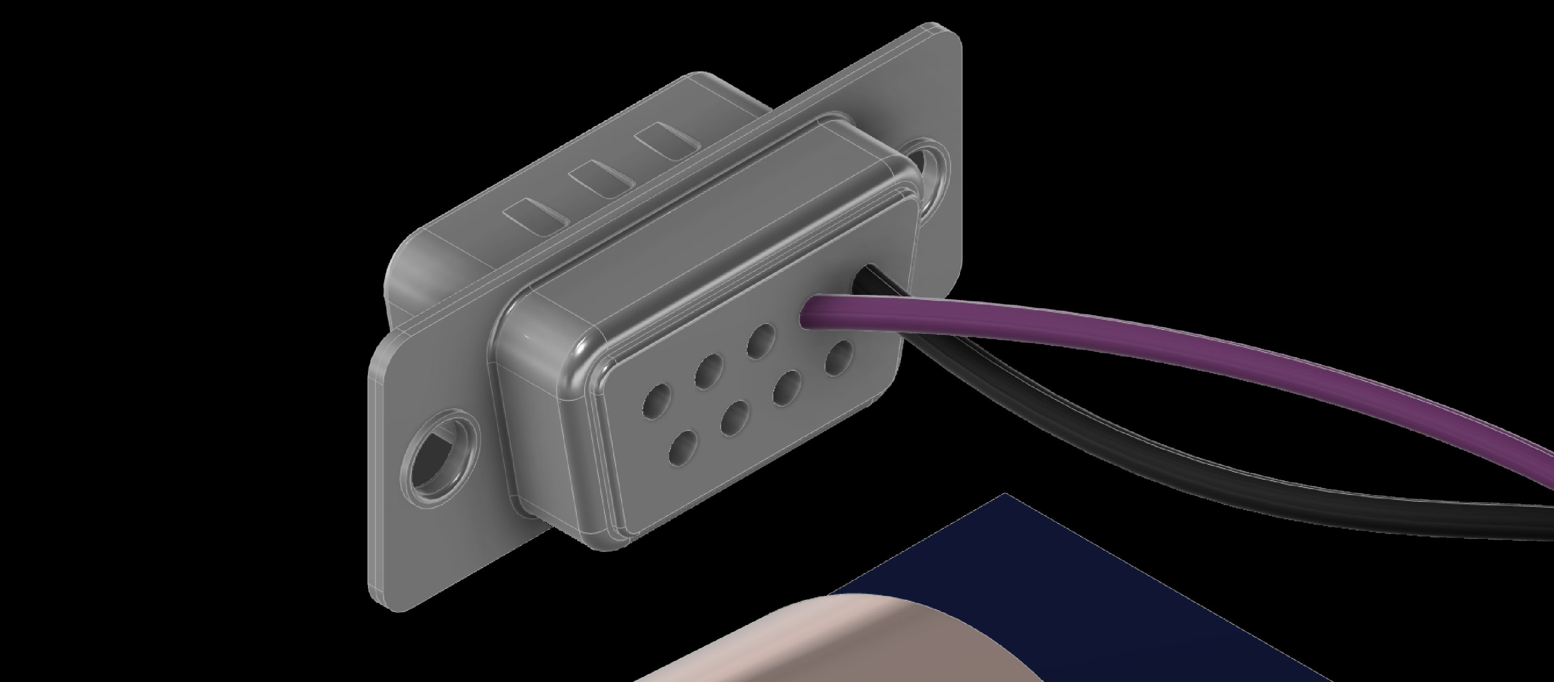
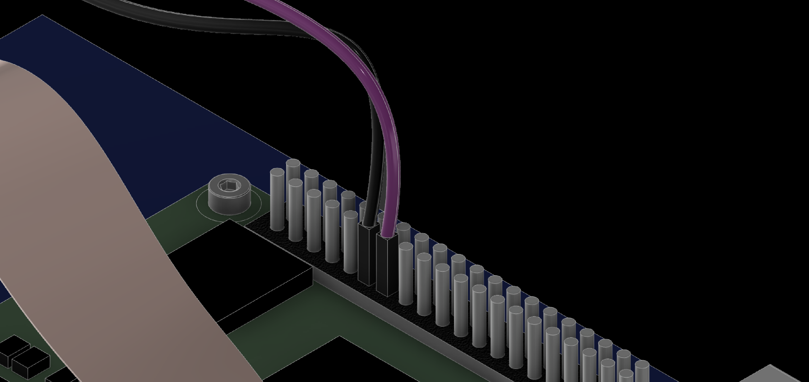
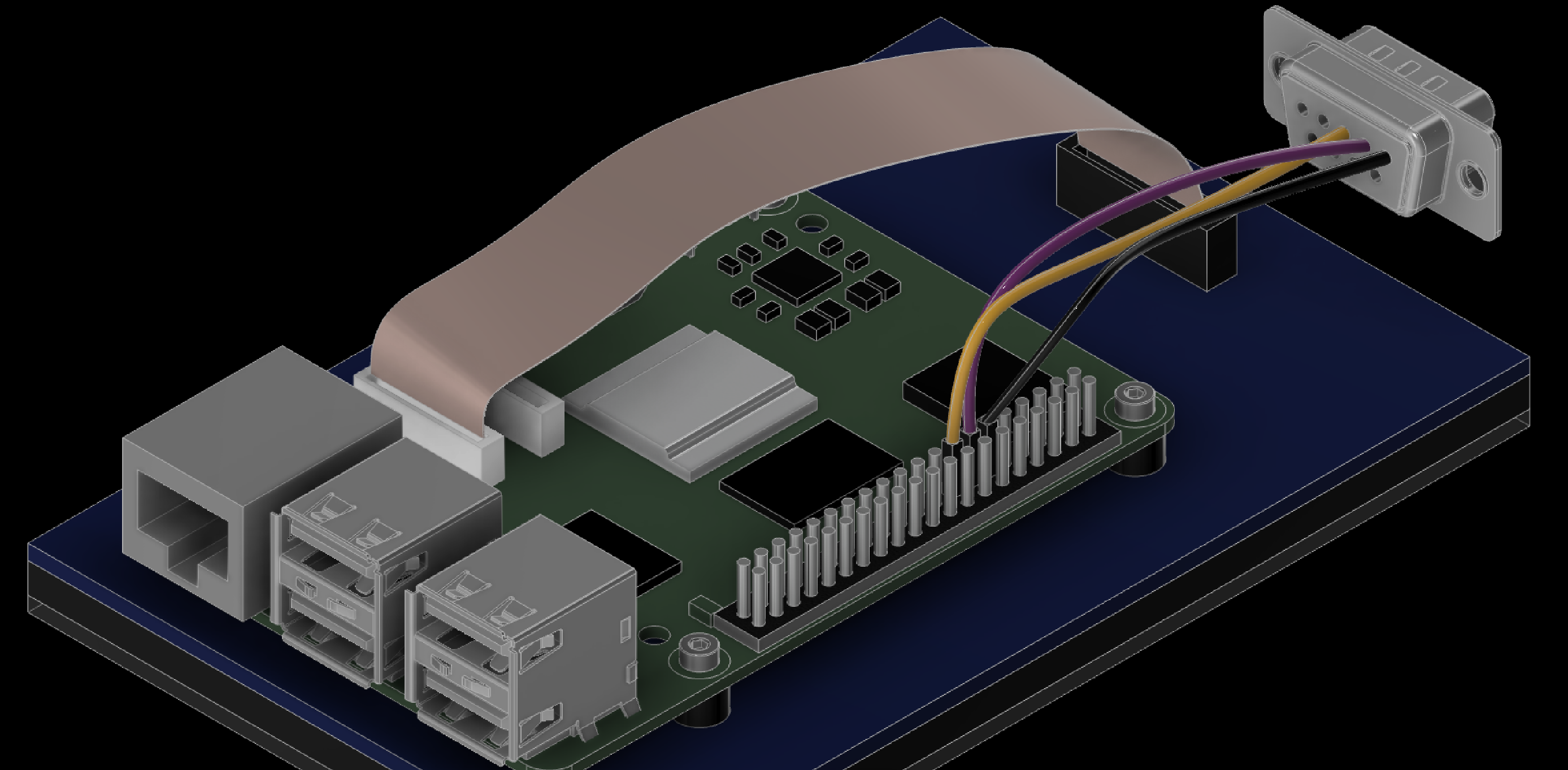
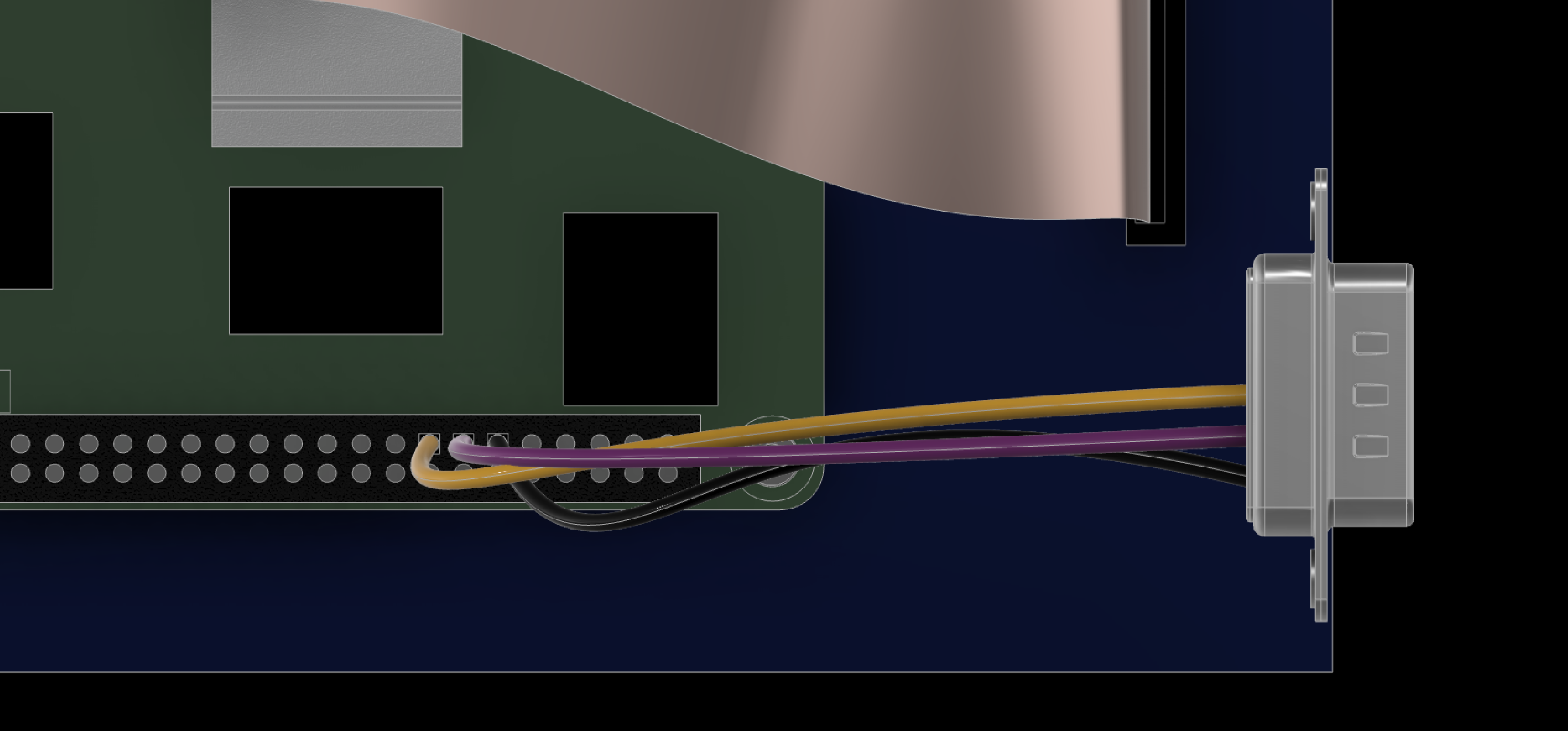
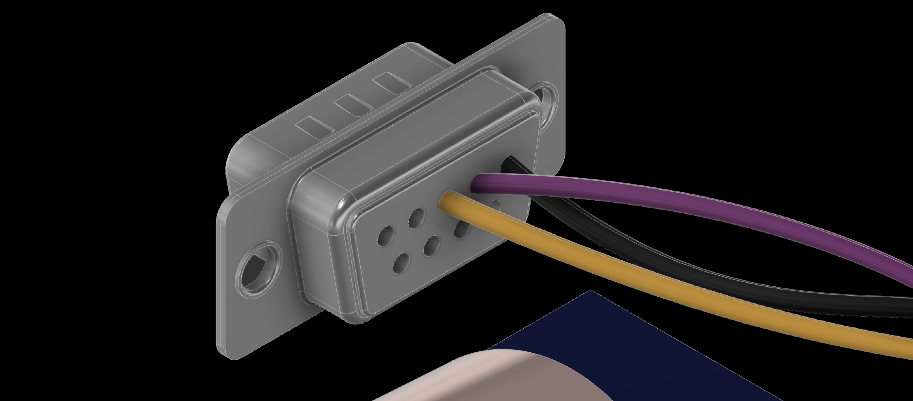
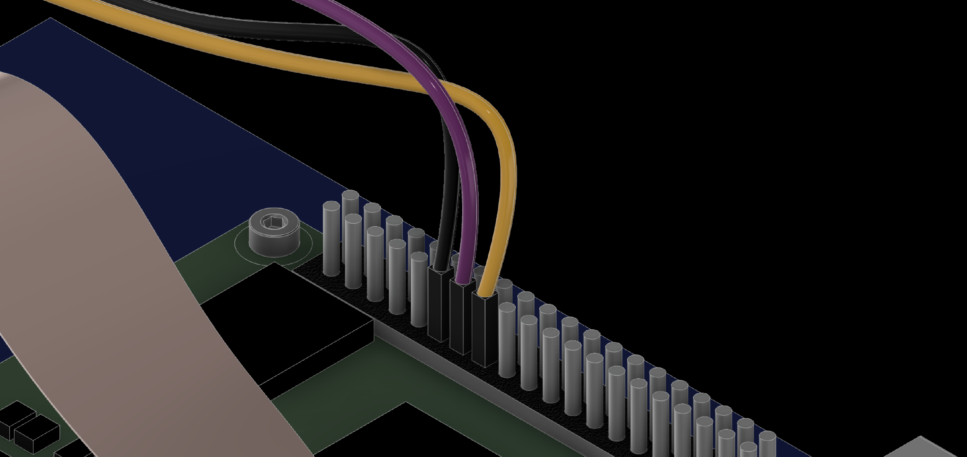
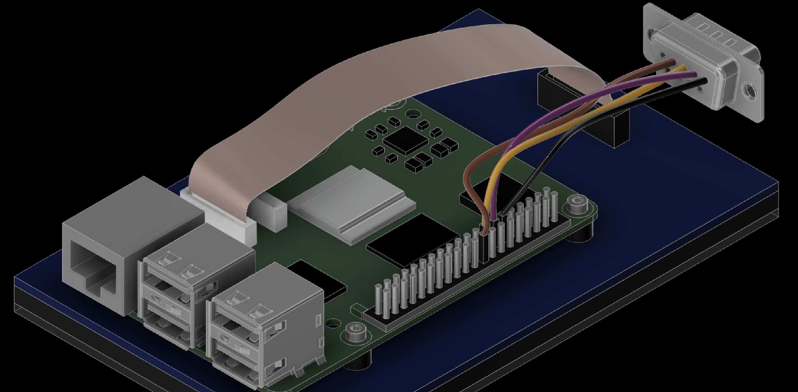
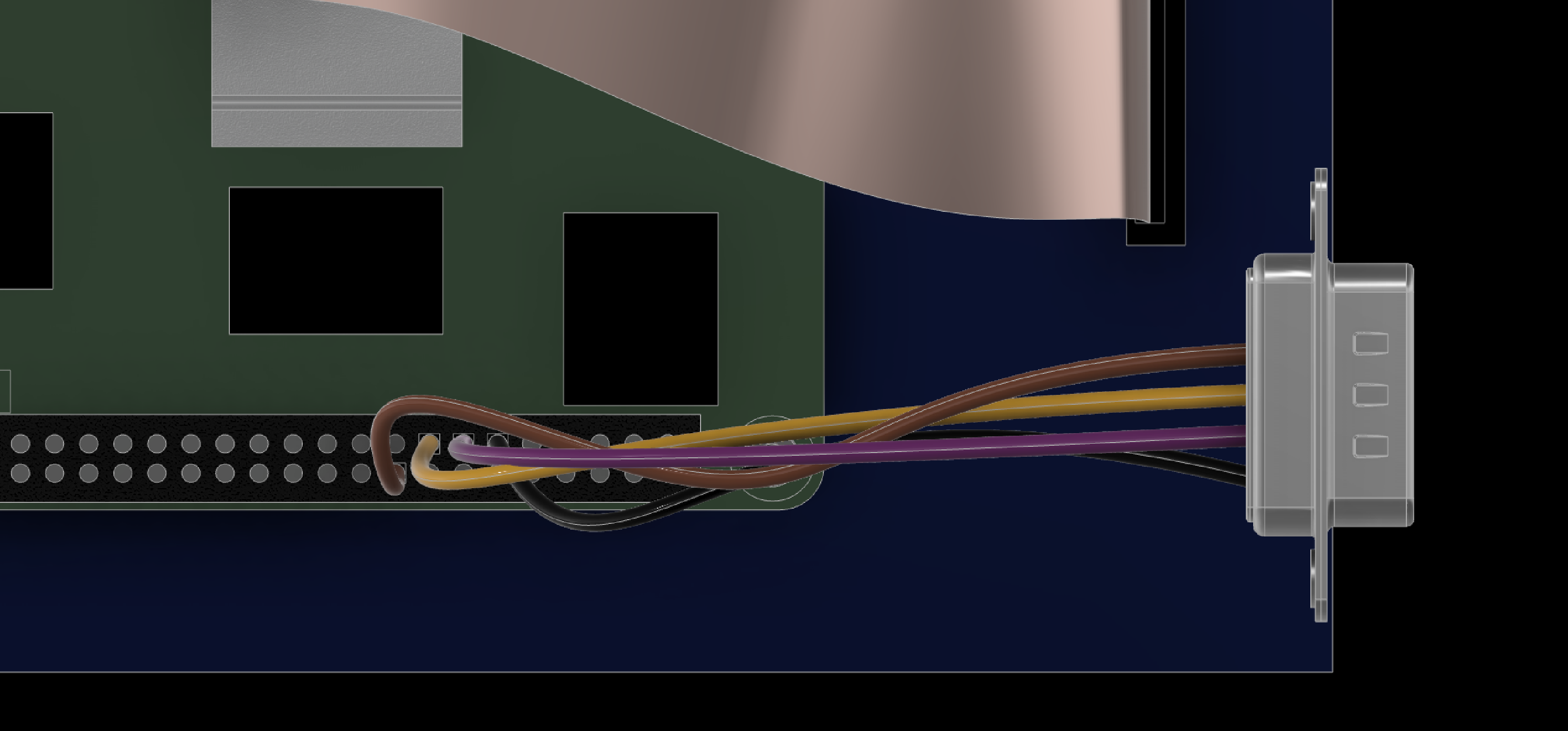
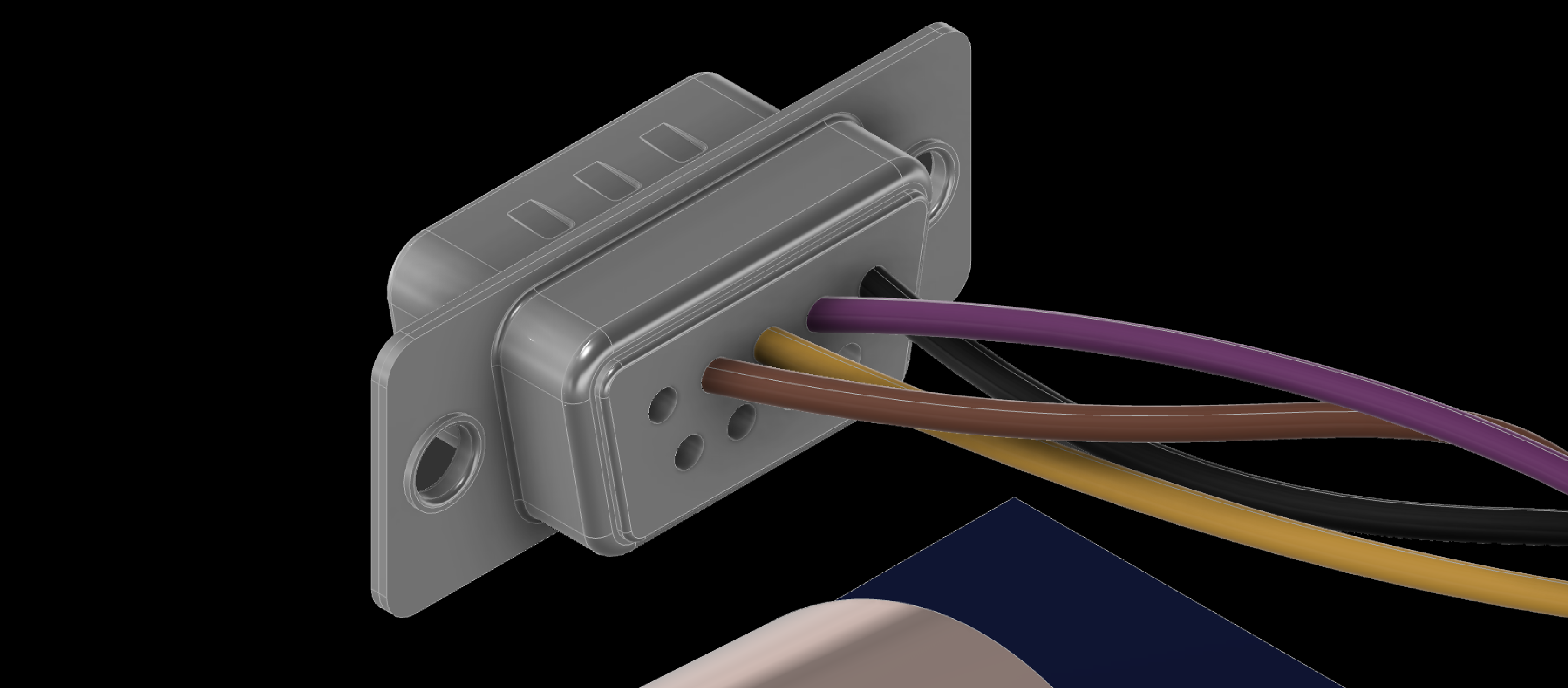
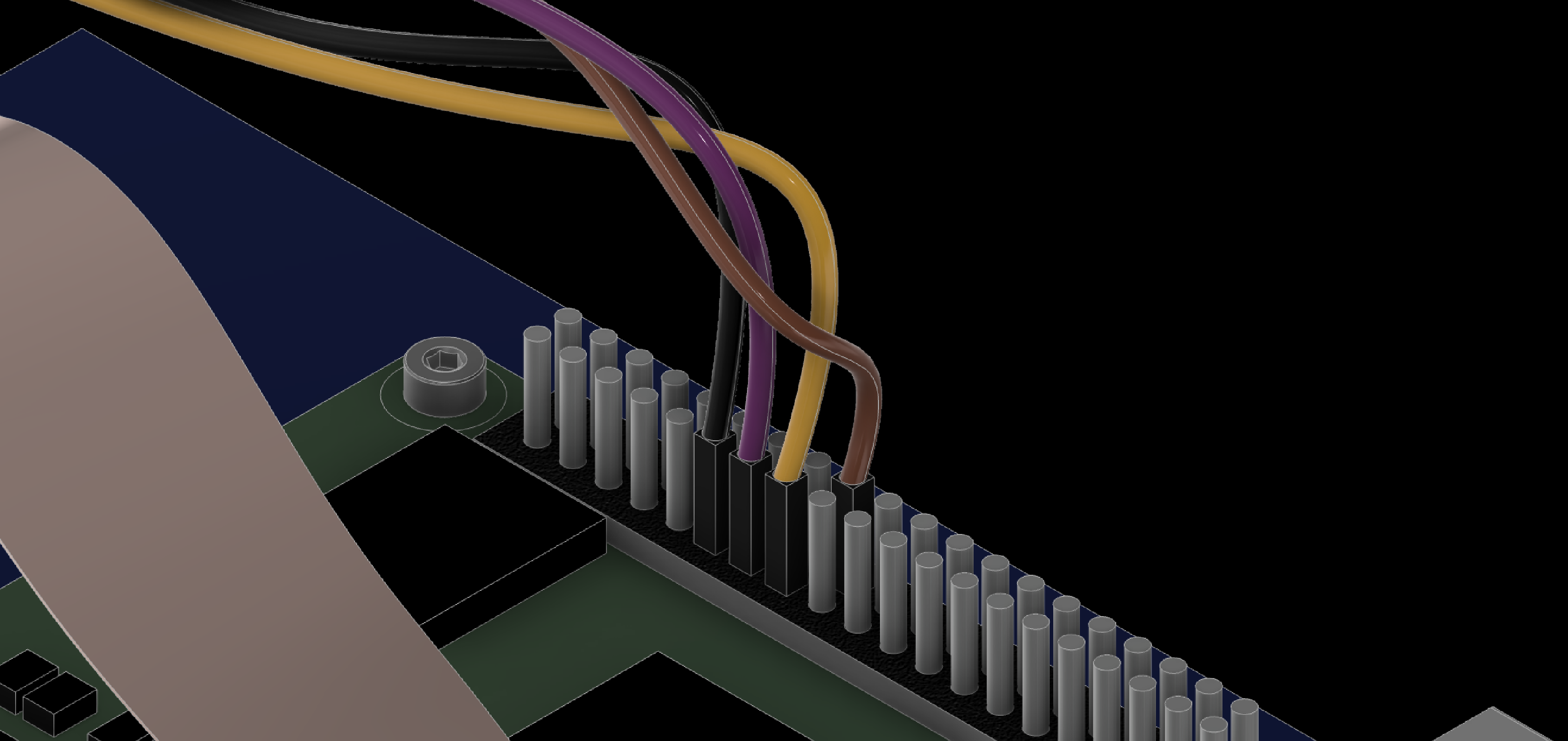
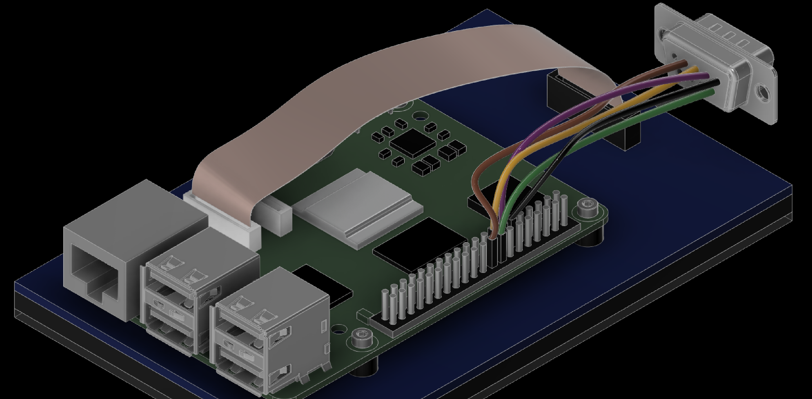
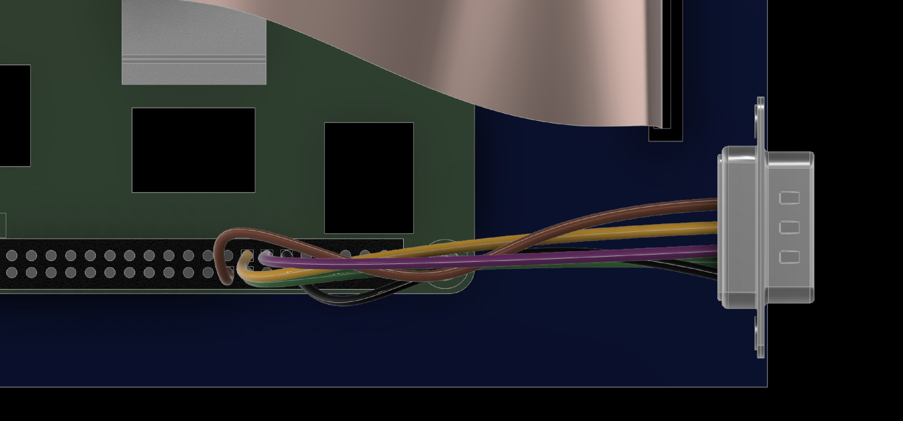
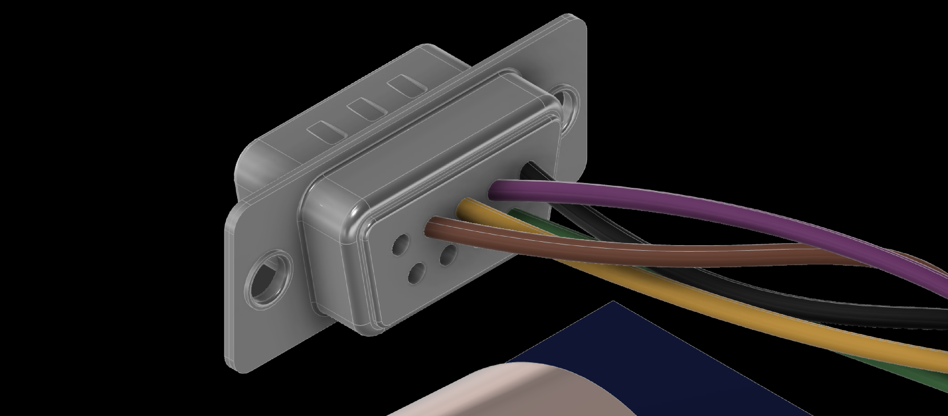
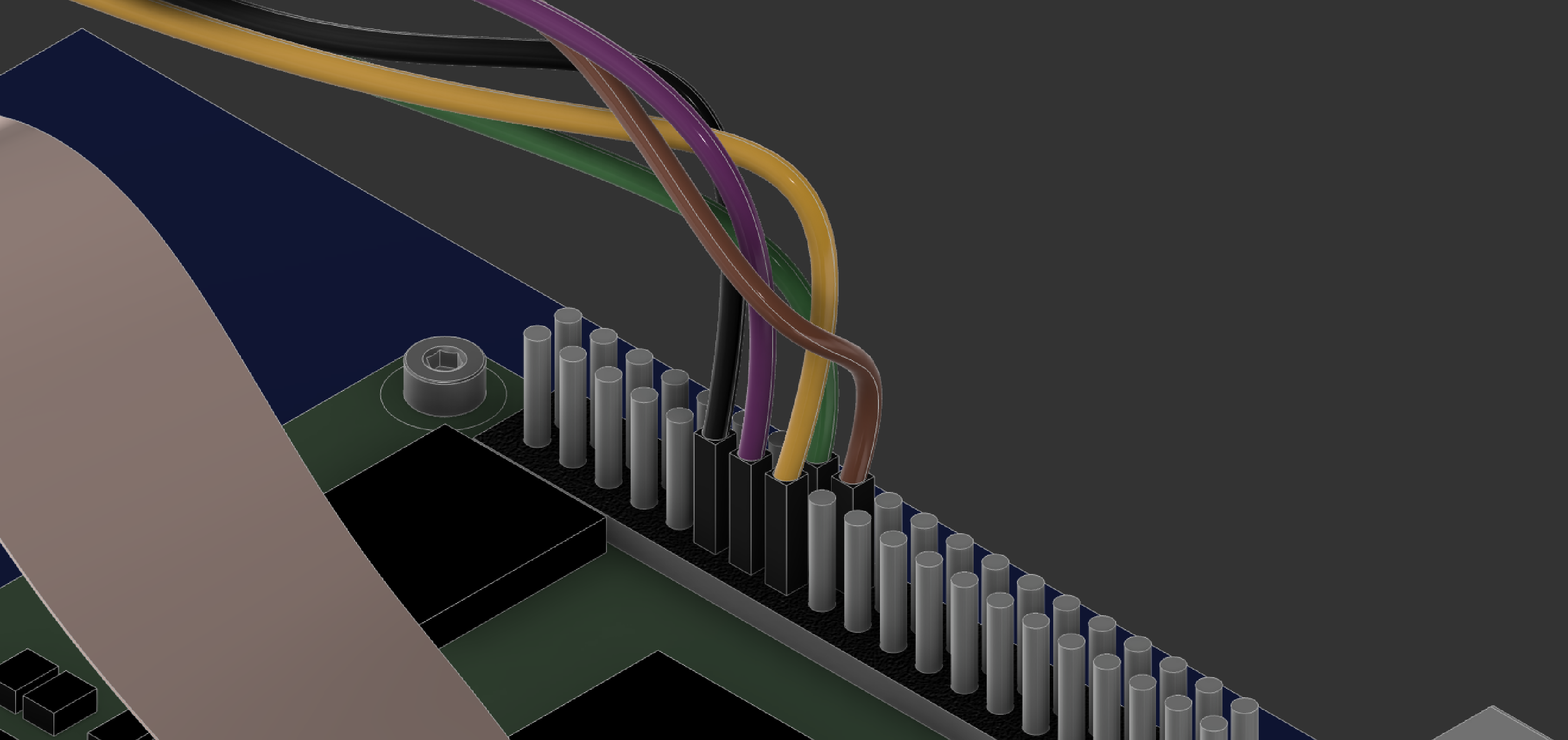
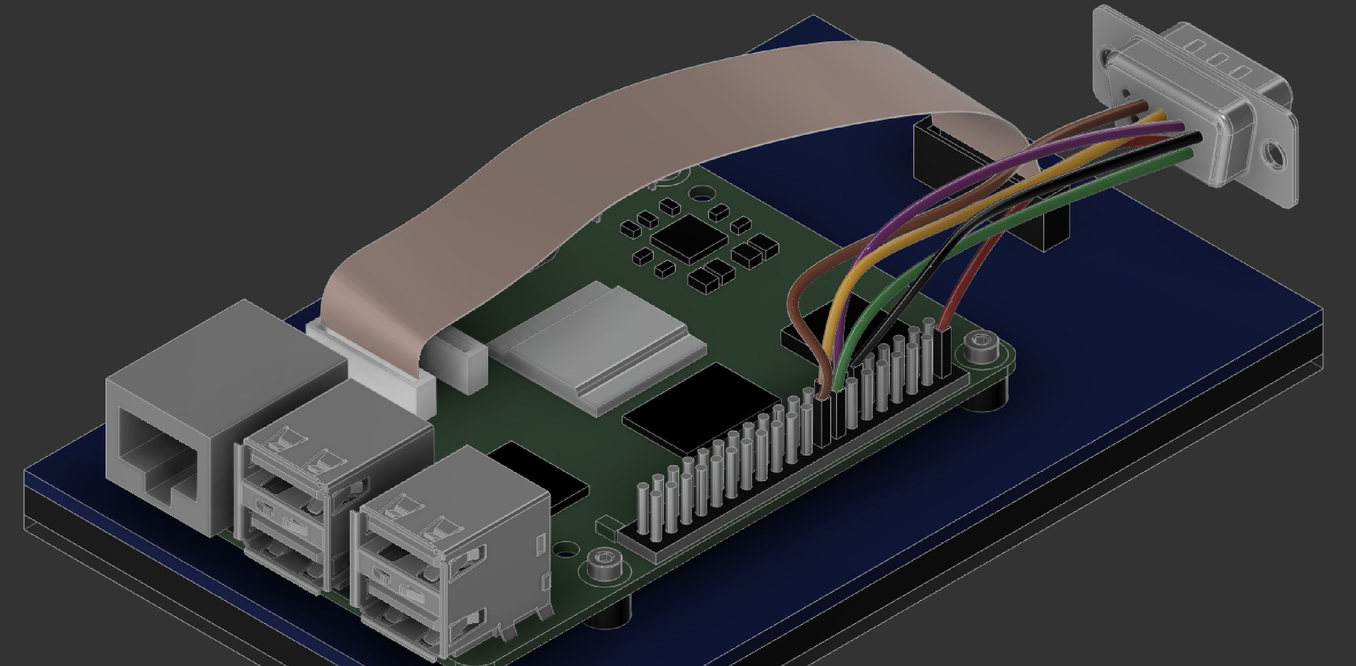
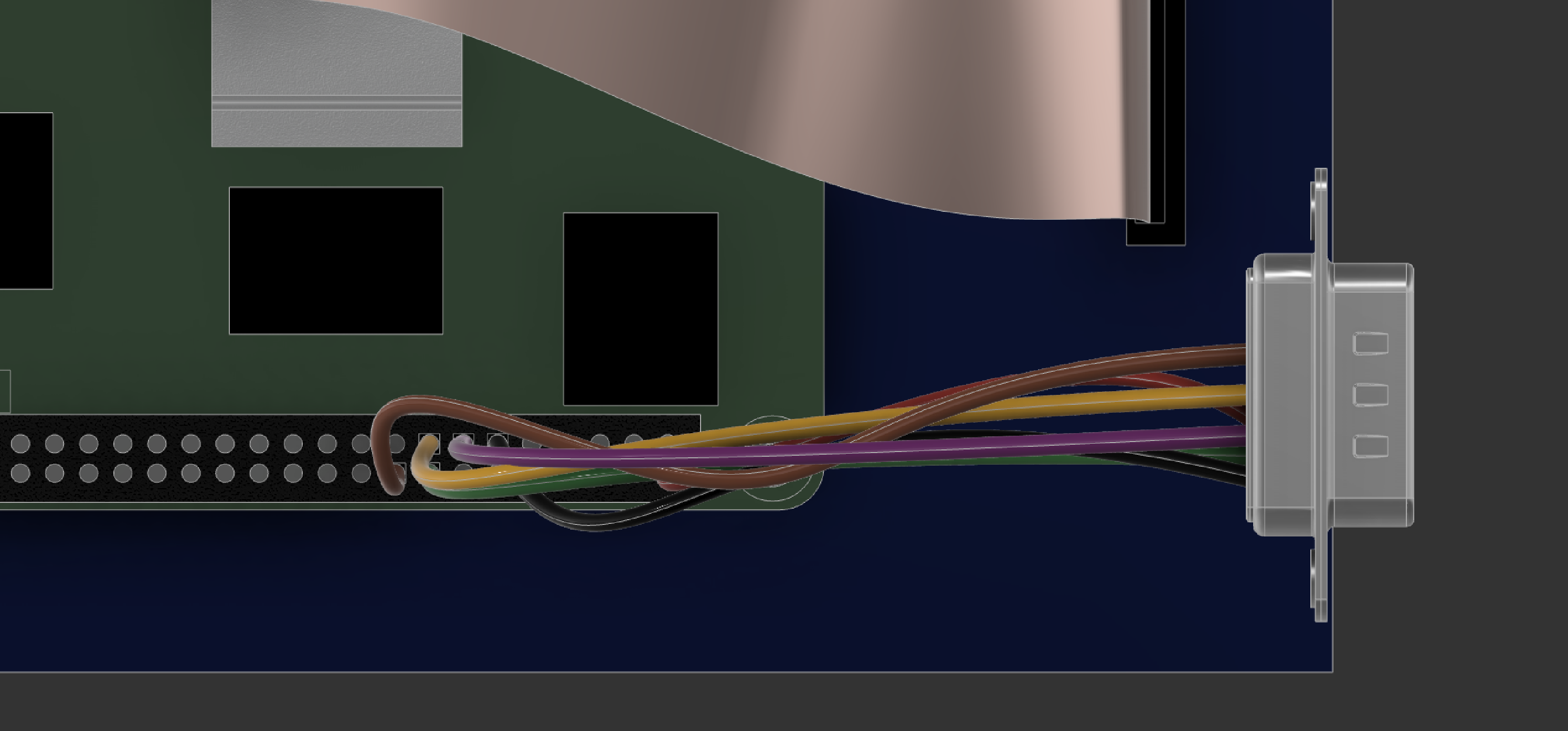
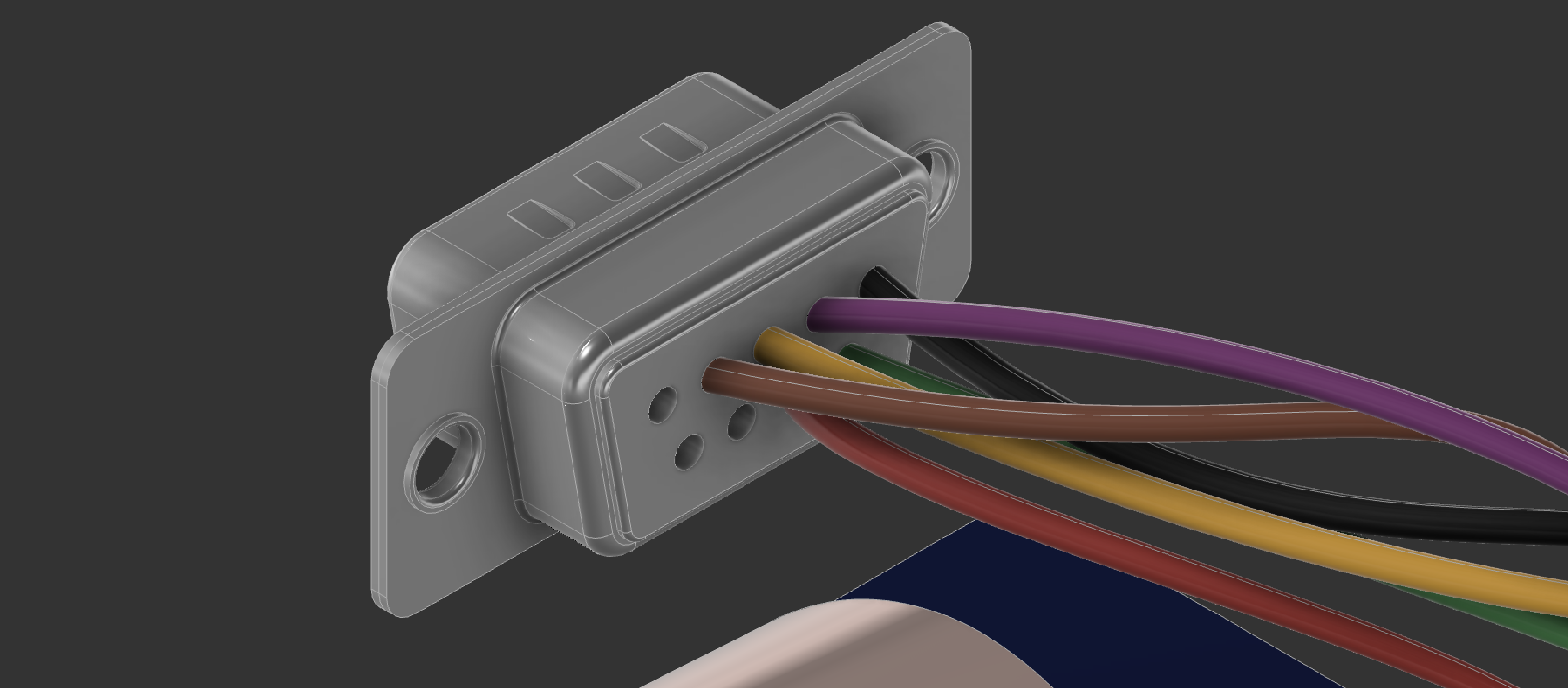
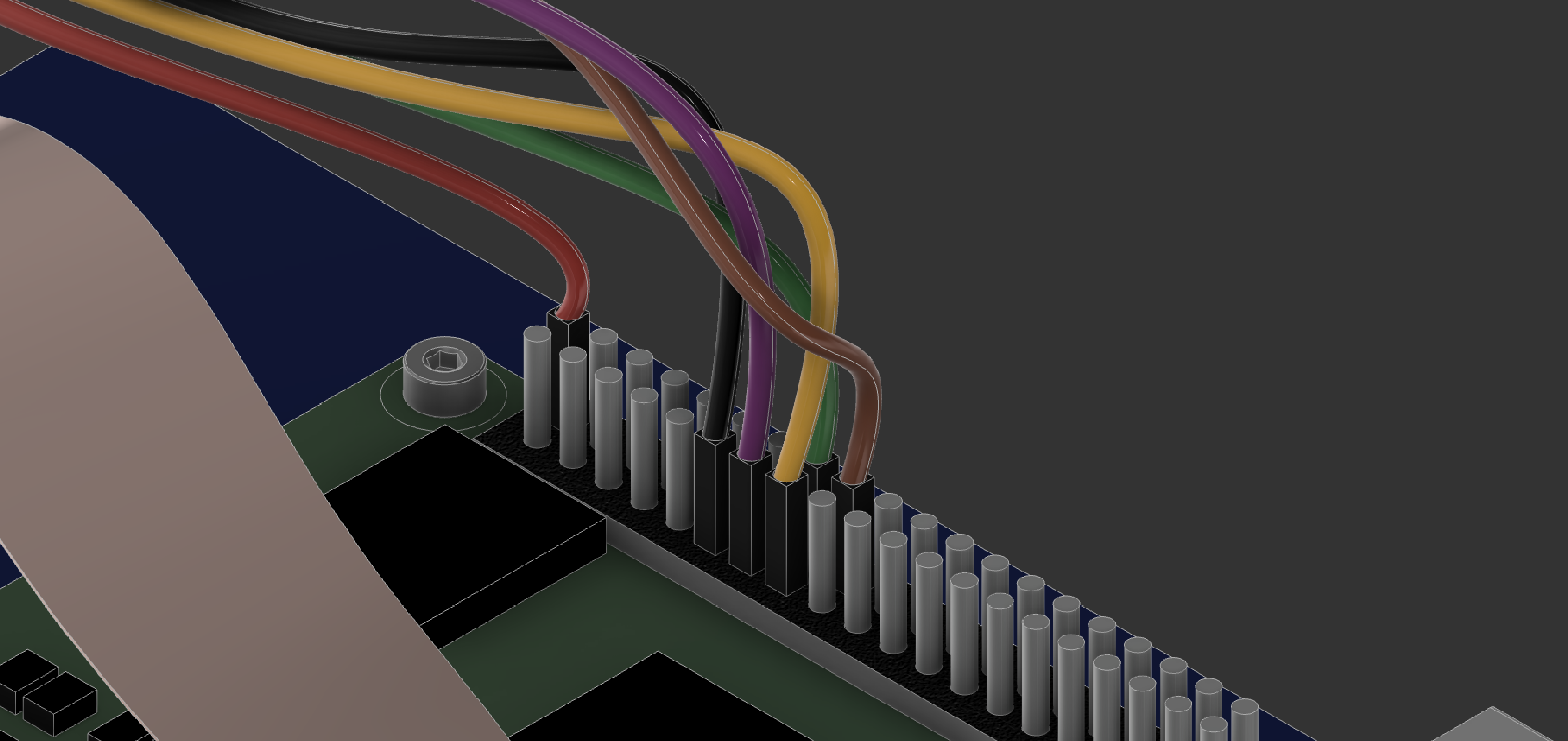
Pin mapping
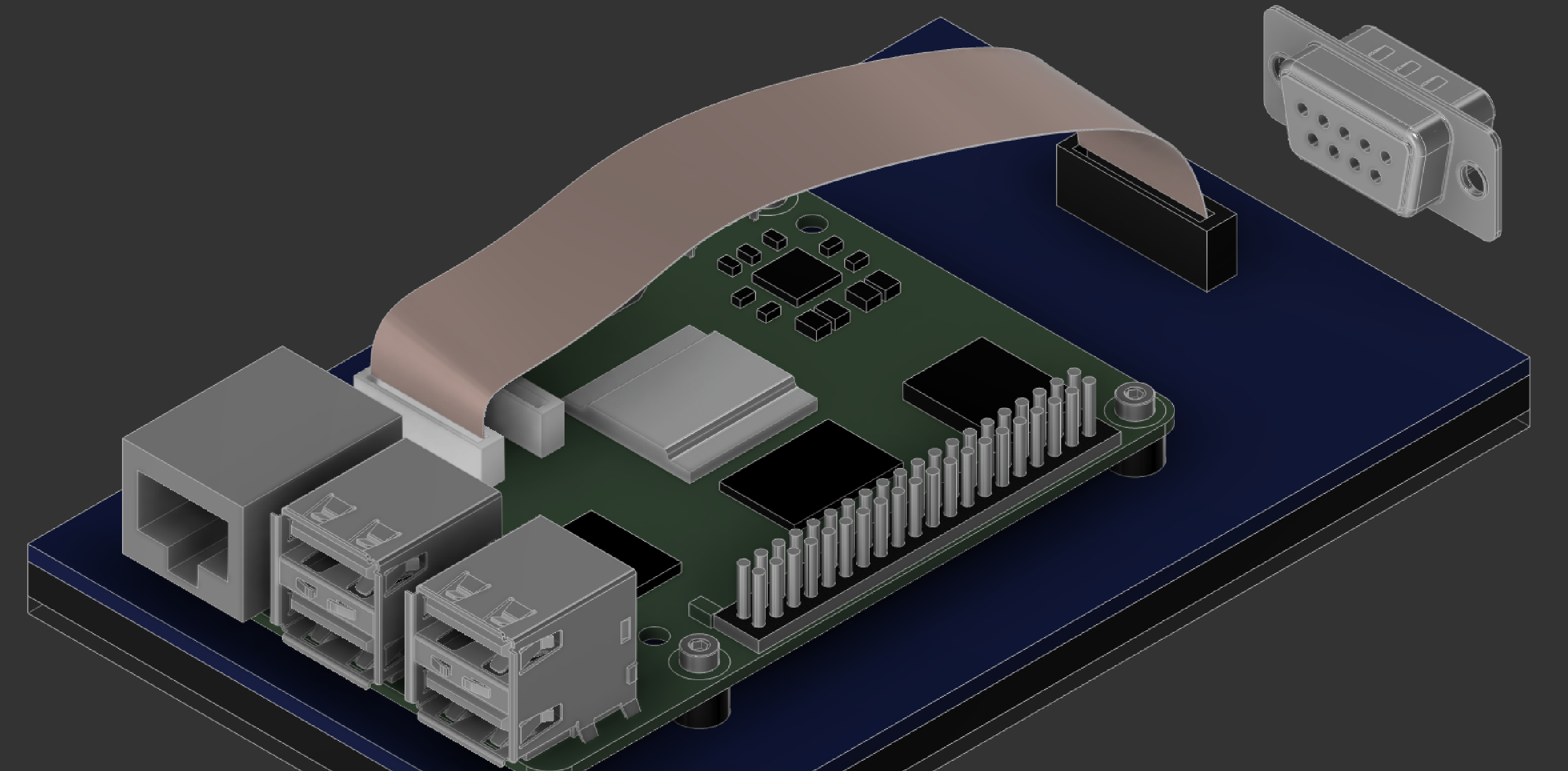
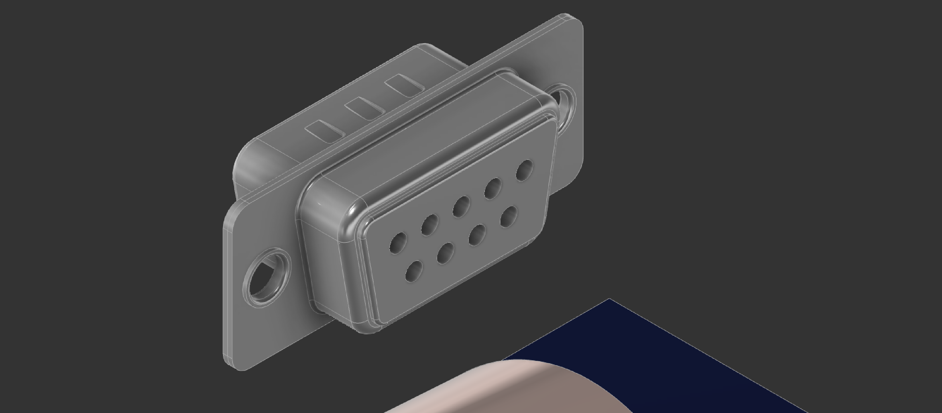
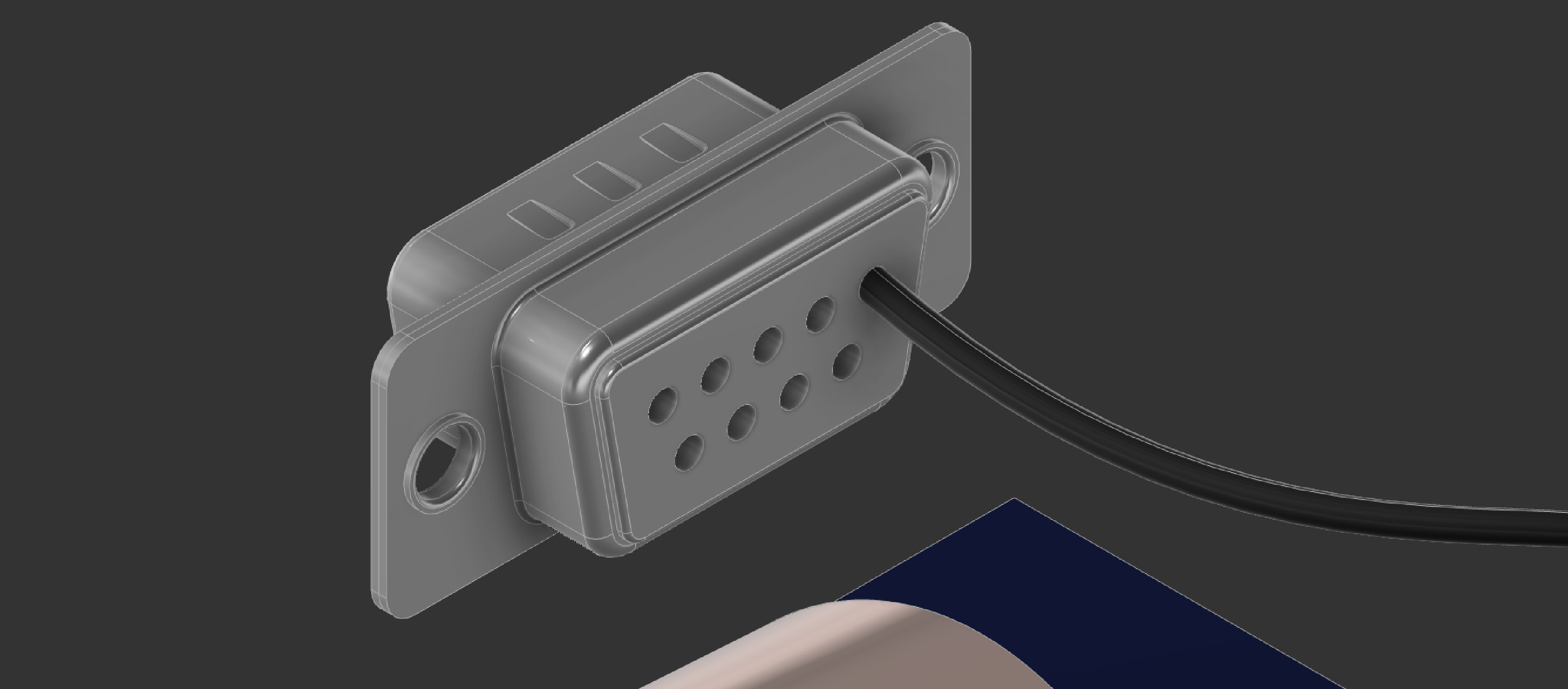
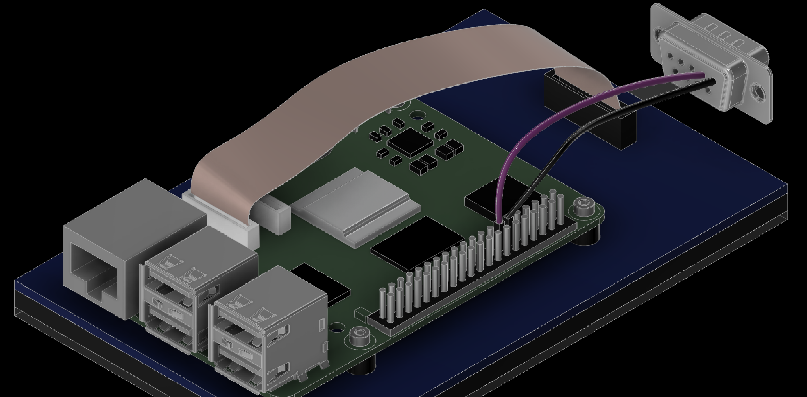
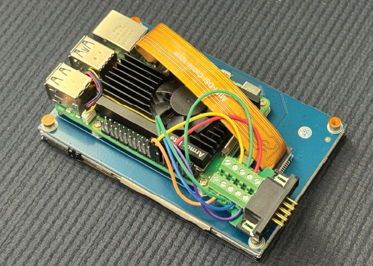
Wire the DB9 connector to the Raspberry Pi 5. Your connector may look different from the illustration.
| DB9 Pin | Pi Pin | GPIO |
|---|---|---|
| 1 | 11 | GPIO 17 |
| 2 | 13 | GPIO 27 |
| 3 | 15 | GPIO 22 |
| 4 | 18 | GPIO 24 |
| 6 | 16 | GPIO 23 |
| 7 (optional) | 2 | 5V |
The 5 volt connection is only needed for the wireless CX40+ joystick.
For a visual guide of the wiring diagram, see the next slides.
4. Wire the DB9 Connector
4.1 Wiring diagram
5. Assemble the Atari Devbox
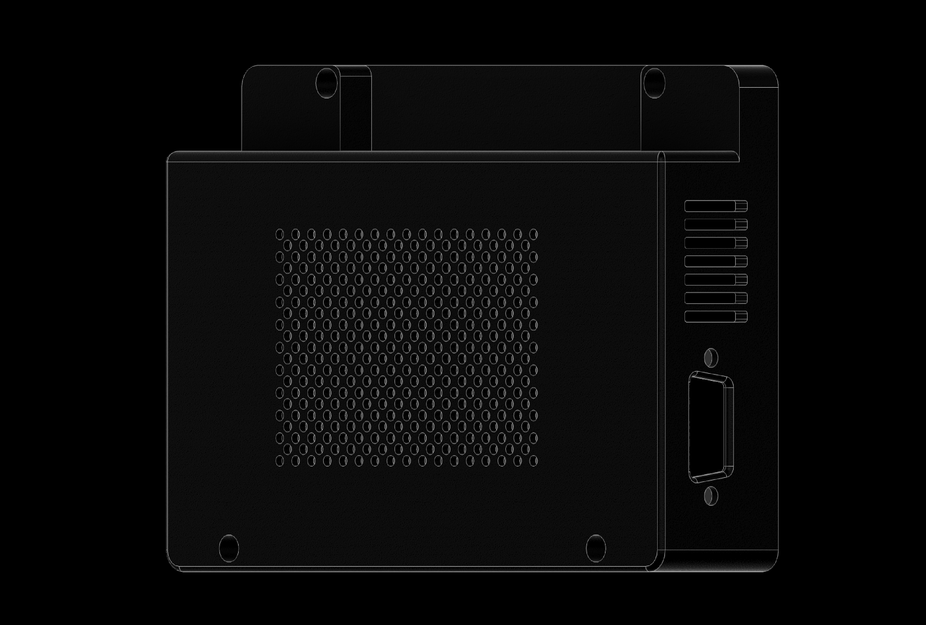
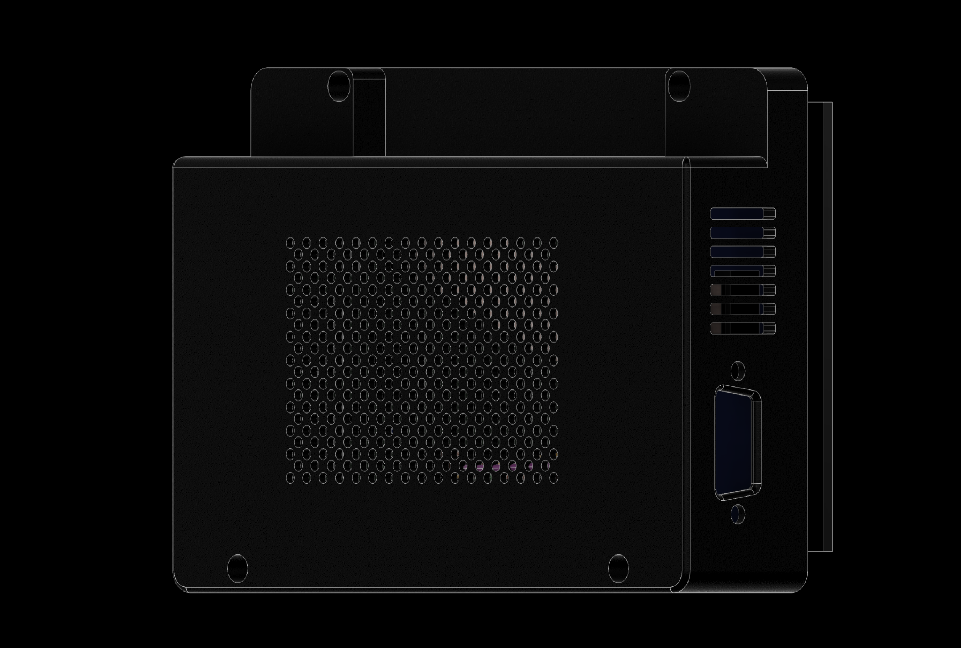
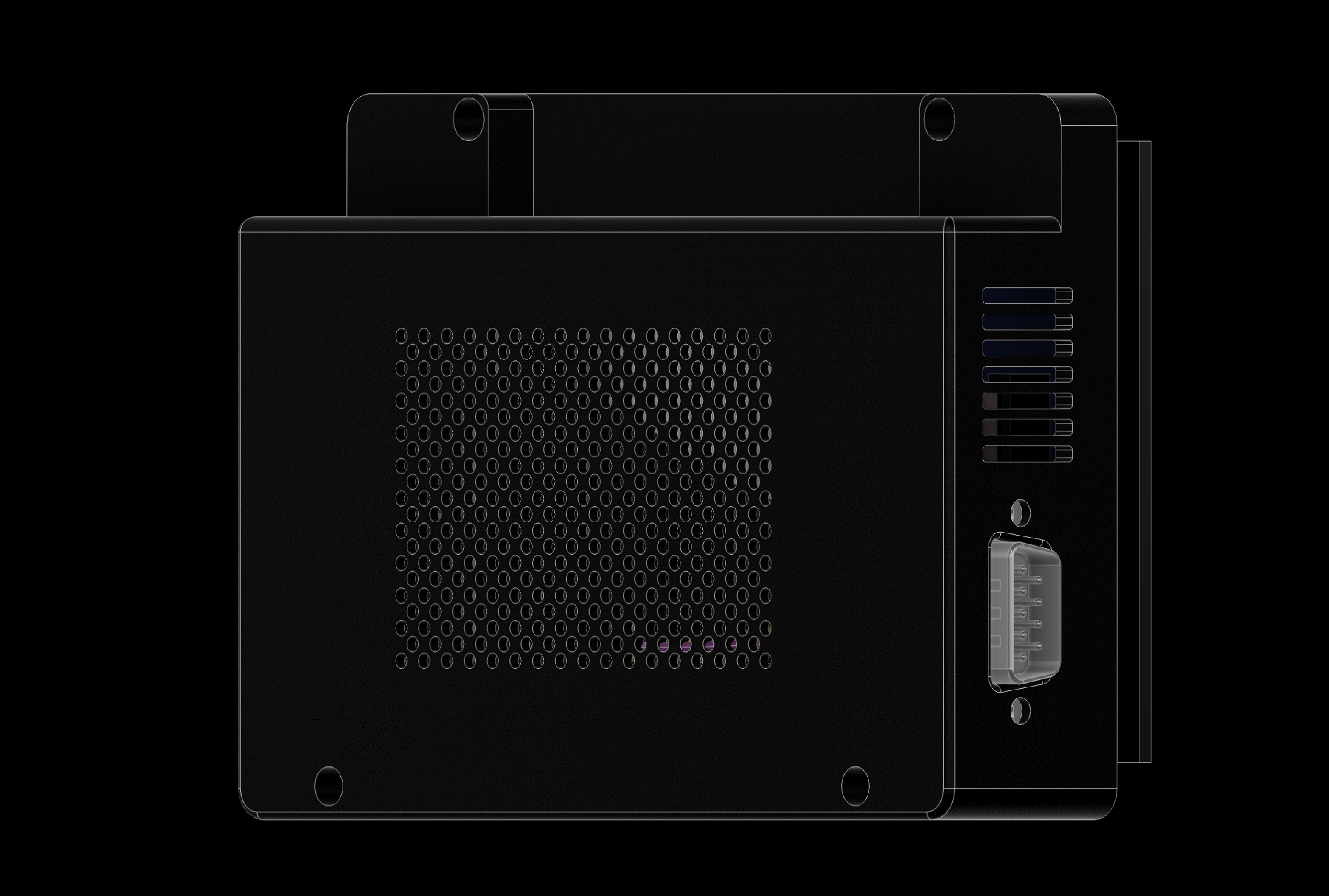
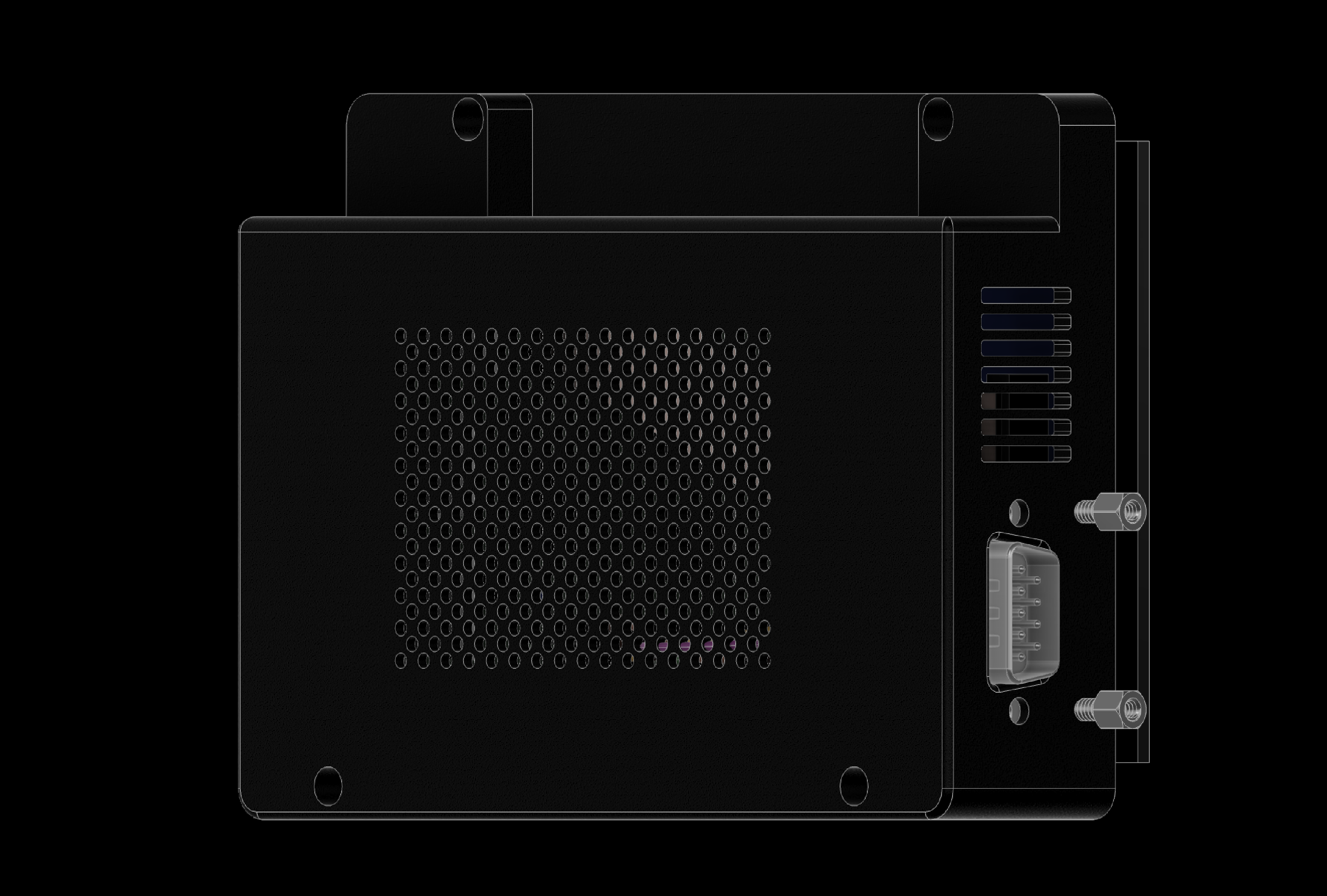
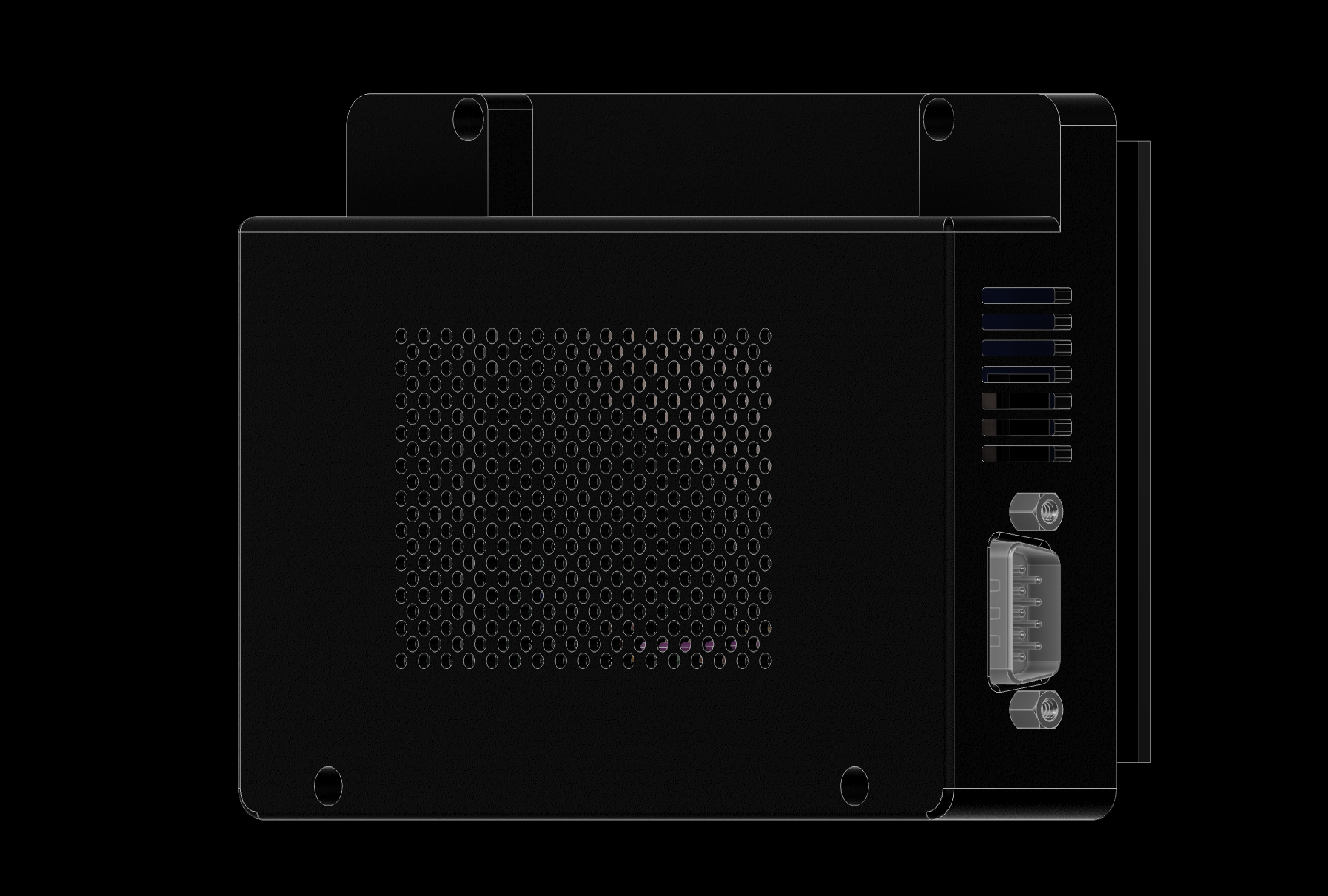
Now connect the DB9 connector to the back chassis.
5. Assemble the Atari Devbox
5.1 DB9 connector
5. Assemble the Atari Devbox
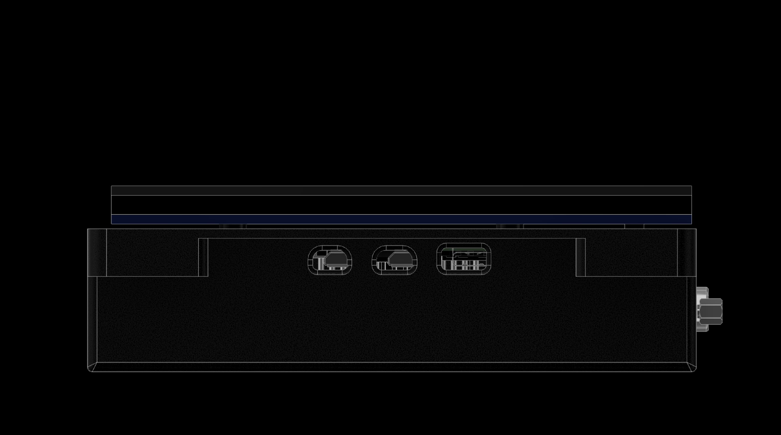
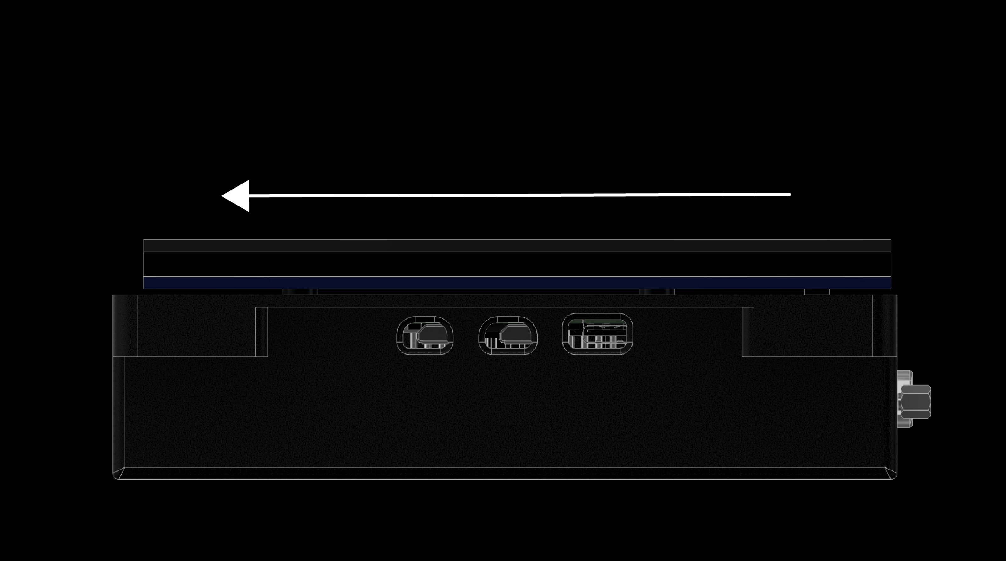
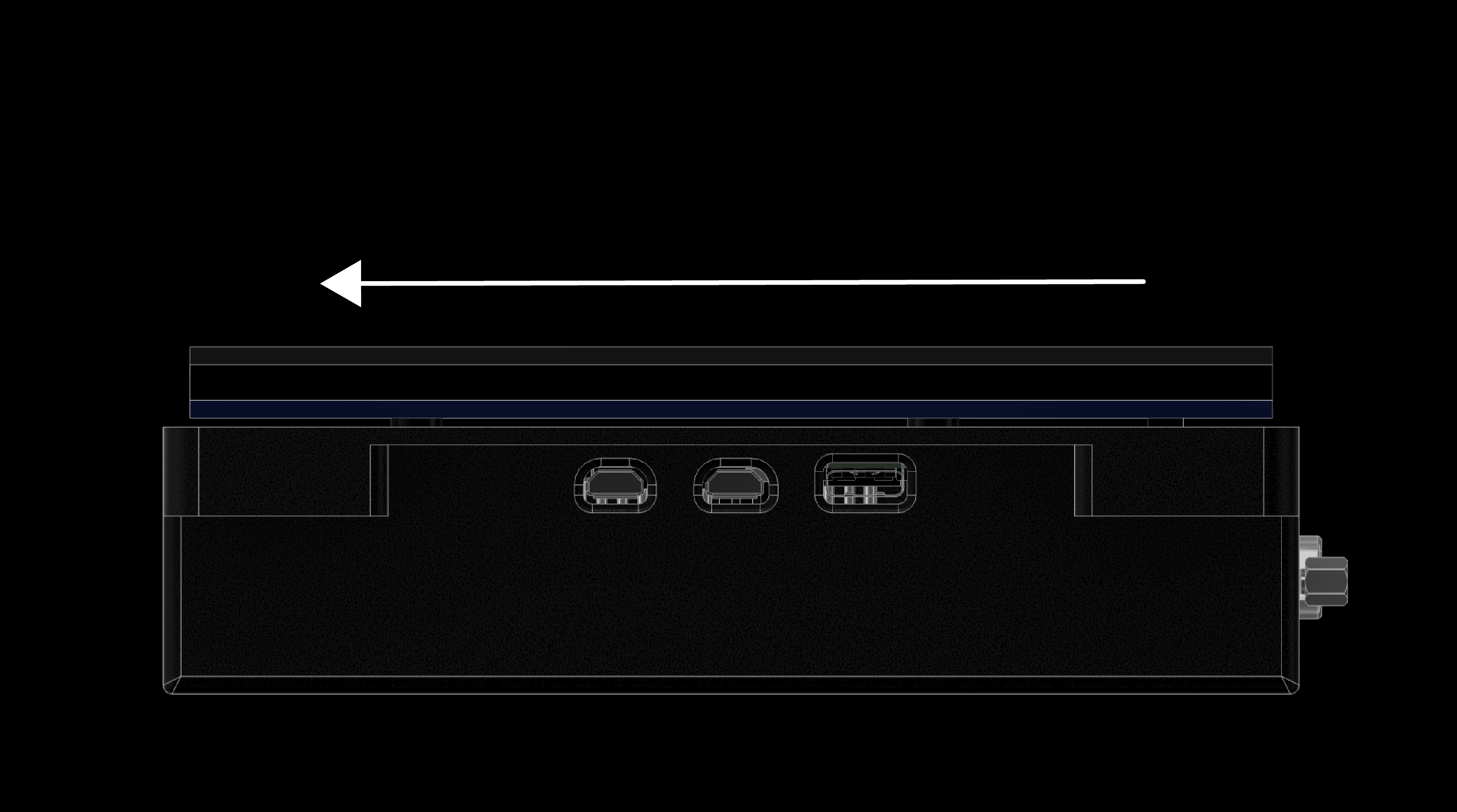
Fit the Raspberry Pi 5 into the back chassis by sliding it into position. The position is correct when all ports are aligned.
5. Assemble the Atari Devbox
5.2 Slide mechanism
5. Assemble the Atari Devbox
5.3 Front cover
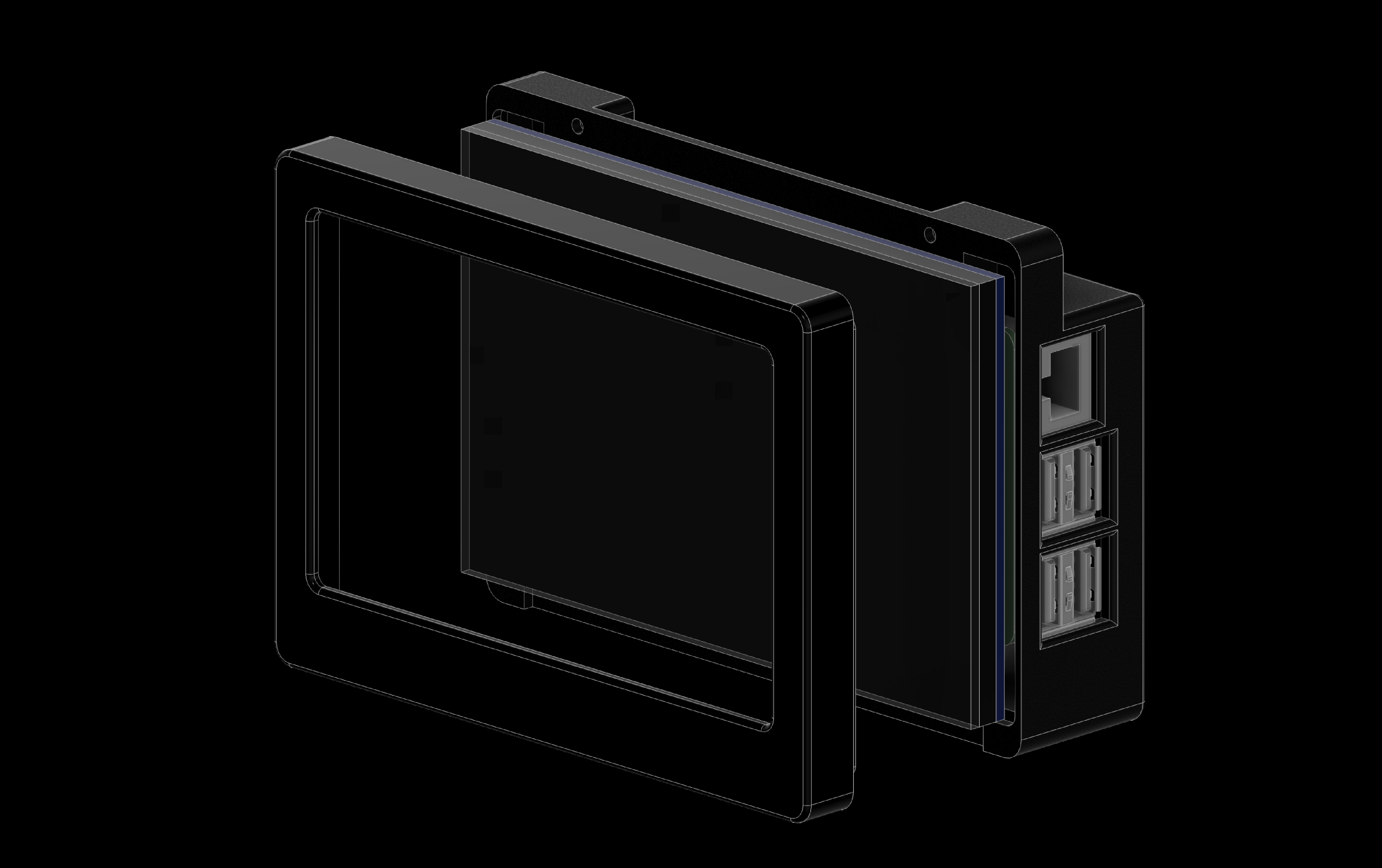
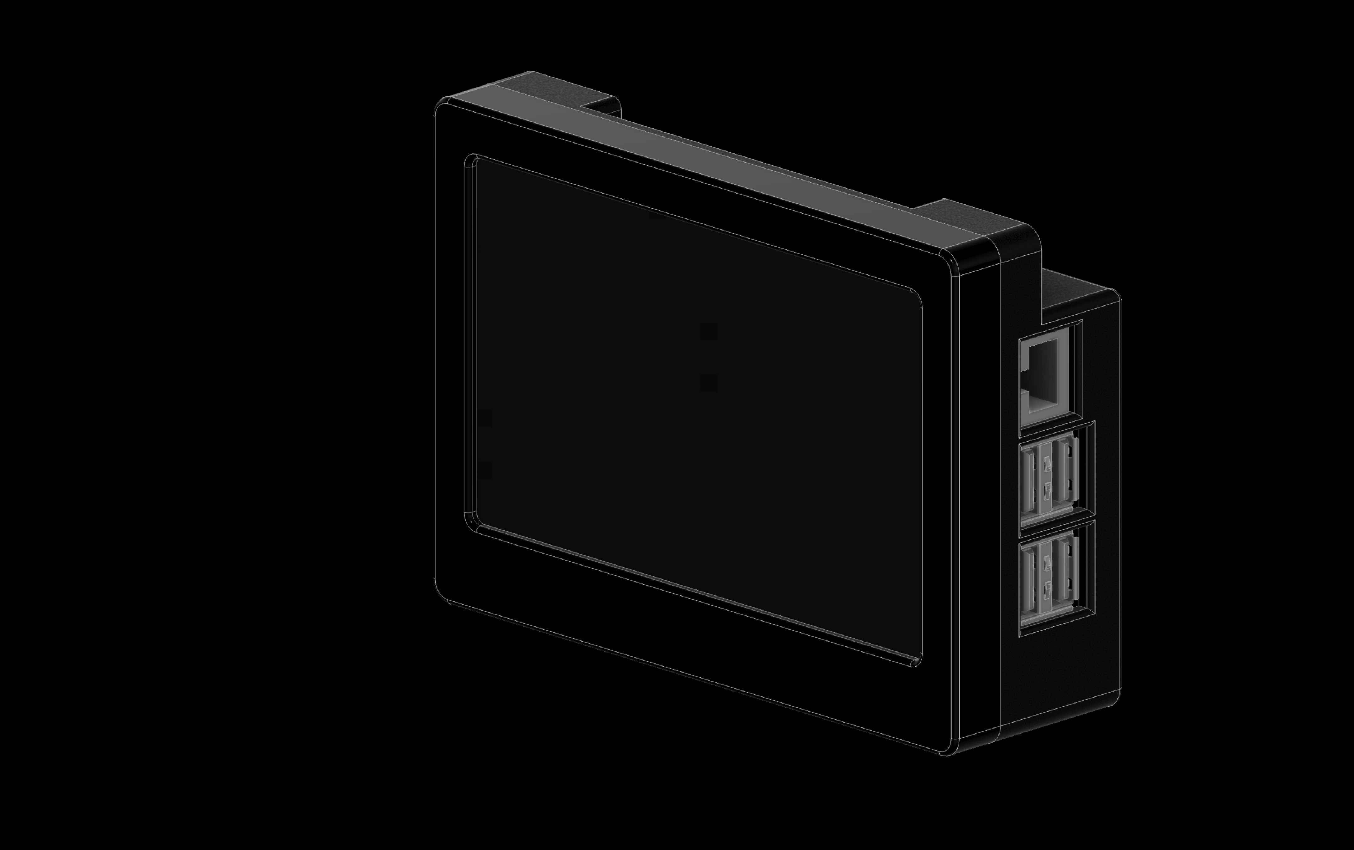
5. Assemble the Atari Devbox
5.4 Back & screws